System and method for recycling asphalt using induction heating

a technology of induction heating and asphalt, which is applied in the field of system and method for recycling used asphalt materials, can solve the problems of loss of structural integrity, water susceptibility (striping), permanent deformation (rutting), bleeding, shoving and cracking,

Active Publication Date: 2017-10-26
CRUPI FRANCESCO A +1
View PDF3 Cites 12 Cited by
  • Summary
  • Abstract
  • Description
  • Claims
  • Application Information

AI Technical Summary

Benefits of technology

[0014]An asphalt processing system is provided. The asphalt processing system is formed from a heating chamber, having a floor, ceiling, and four walls, a transfer system and an induction heating system. The heating chamber includes an input is disposed on the ceiling or an upper half of one of the walls, and an output is disposed on the floor or within a lower half of one of the vertical walls...

Problems solved by technology

Some major problems associated with the performance of hot mix asphalts (HMA) pavements can be moisture susceptibility (striping), permanent deformation (rutting), bleeding, shoving, and cracking (thermal and fatigue).
As the asphalt stiffens, fatigue resistance decreases significantly, resulting in cracking and loss of structural integrity (Glover, et al., Evaluation of binder aging and its influence in aging of hot mix asphalt concrete: literature review and experimental design.
The superheating causes material formation on the dryer, hot elevator and screen tower, requiring extensive clean up or replacement of those parts.
More importantly, the heat transfer from the superheated material results in release of maltenes from the asphalt, as seen by the excessive smoke formation, and causes premature aging of the virgin asphalt, i.e. rapid oxidation due to the high temperatures.
For example, when cold wet RAP...

Method used


Image

  • System and method for recycling asphalt using induction heating
  • System and method for recycling asphalt using induction heating
  • System and method for recycling asphalt using induction heating

Examples


example 1

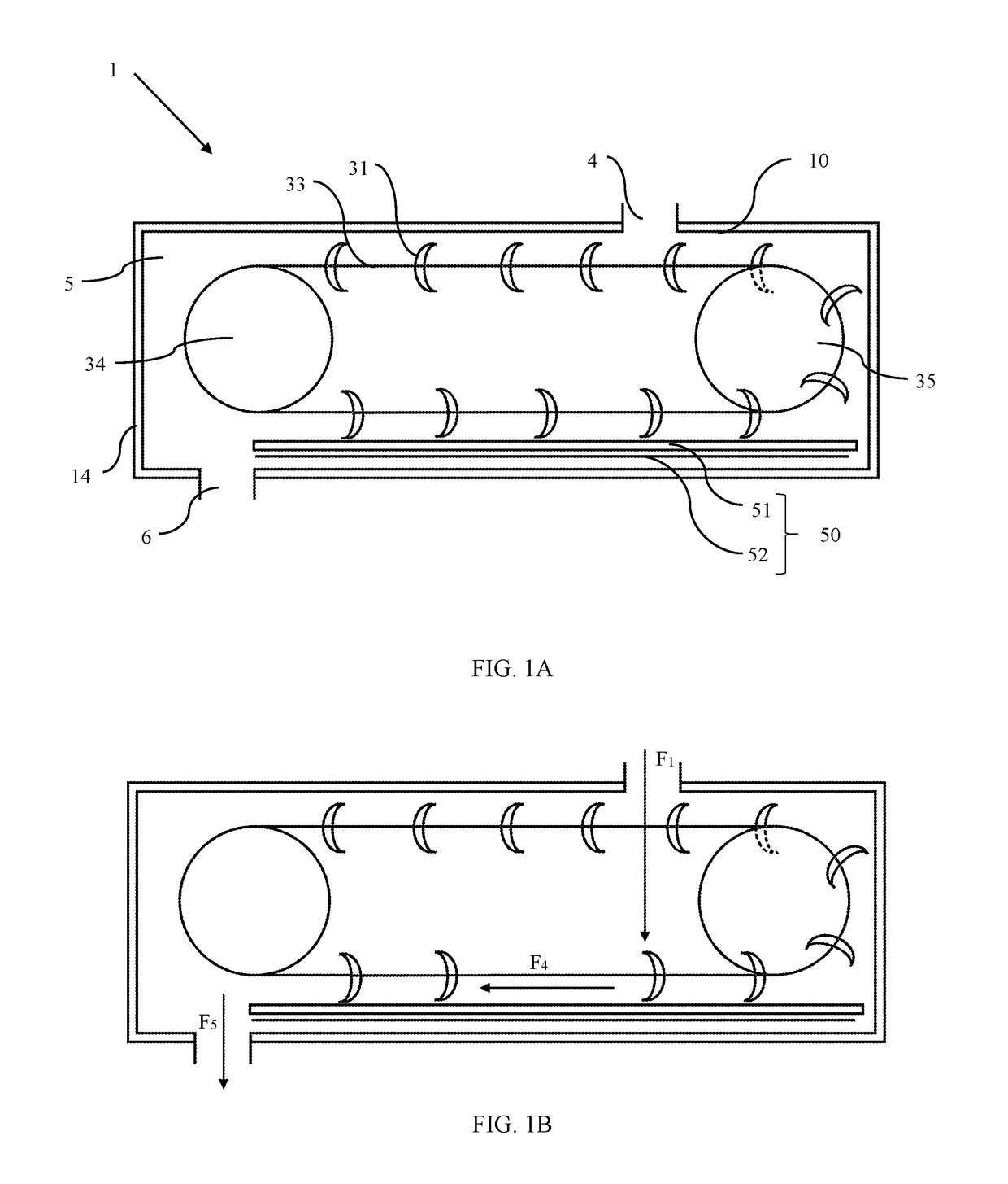
[0058]RAP processor 1 is composed of RAP transfer system 30 and induction heating system 50, as seen in FIG. 1A. RAP transfer system 30 and induction heating system 50 are enclosed in heating chamber 5, which comprises chamber wall 10, and has input 4 for accepting asphalt cement at one end of the RAP processor and output 5 for releasing heated asphaltic concrete from RAP processor 1 opposite input 4. Wall insulation 14 is formed of Fiberfax® alumina-silica insulation and disposed on wall 10 to limit heat transfer and escape from RAP processor 1. RAP transfer system 30 is composed of chain sprocket set 34 and ancillary chain sprocket set 35, which are rotatably mounted to chamber wall 10 or a frame in RAP processor 1. One chain sprocket set, such as chain sprocket set 34 is in mechanical communication with a drive system. Without limiting the scope of the invention, as an example chain sprocket set 34 is attached to a drive shaft that extends through chamber wall 10. The drive shaft...

example 2

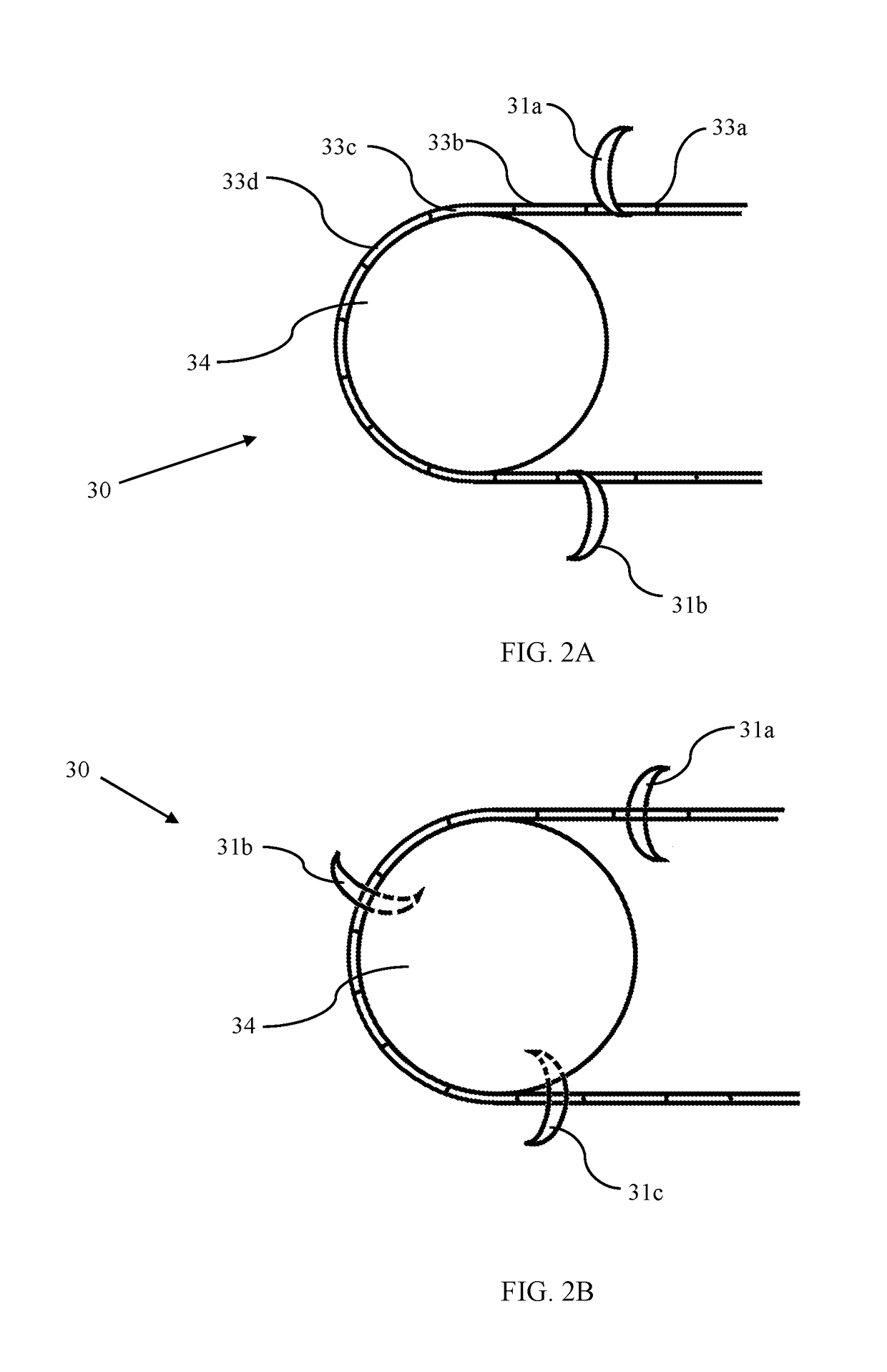
[0061]RAP transfer system 30 can vary based on the desired characteristics of the system. The RAP transfer system is formed of two sprockets sets on either side of the RAP processor, i.e. first chain sprocket set 34a and second chain sprocket set 34b on one end of the RAP processor and first ancillary chain sprocket set 35a and first ancillary chain sprocket set 35b on the opposite end of the RAP processor. The distance between first chain sprocket set 34a and second chain sprocket set 34b or first ancillary chain sprocket set 35b is sufficient to permit paddle 31 to pass between the sprocket set. This allows paddle 31 to be attached to paddle chain 33 in various configurations. For example, paddle 31 can have attaching points on the lower edge of the paddle, as seen in FIG. 2A, or at the middle of the paddle, as seen in FIG. 2B. Paddle chain 33 is formed of a plurality of sections, 33a, 33b, 33c, 33d, etc., with each paddle attached to a single section of chain. Paddle 31 further c...

example 3

[0063]RAP processor 1 optionally includes at least one convection system 70, seen in FIG. 4. The at least one convection system works to blow heat towards the used asphalt cement (RAP), providing convectional heat, which heats asphalt not directly contacting the induction plate, as well as allowing asphaltic concrete to retain heat as it leaves the induction plate. Convection system 70 consists of blower 71, with convection system input 72 attached to the blower input and convection blower output 73 disposed on the blower output.

[0064]Convection system input 72 can be a duct allowing air to collect from the interior lumen of RAP processor 1. Alternatively, convection system input 72 can comprise a duct transferring air from the interior of RAP processor 1 to a water condenser. The water condenser can be any system allowing water to separate from ambient air, such as an enclosed space disposed separately from the interior of the RAP processor.

[0065]Convection blower output 73 include...


PUM

PropertyMeasurementUnit
Temperatureaaaaaaaaaa
Magnetic fieldaaaaaaaaaa

Abstract

An asphalt processing system is formed from a heating chamber, a transfer system and an induction heating system. A plurality of paddles, conveyor flights, or conveyor belts having a U-shaped blade move the asphalt through the system while concurrently mixing the material to ensure consistent temperatures through the asphalt cement. The asphalt is heating using one or more induction heating systems to quickly heat the asphalt to between 300° F. and 350° F. The system can include a convection system designed to collect air from the heating chamber, further heat it, and recirculate the air to enhance the asphalt heating. A water condenser can be employed to remove moisture during air recirculation, reducing moisture content in the asphalt cement. The asphalt cement is optionally then modified by addition of one or more rejuvenation oils. This system is particularly useful for recycled asphalt pavement, but can be used for all asphalt products.

Description

CROSS REFERENCE TO RELATED APPLICATIONS[0001]This application is a continuation-in-part application of U.S. application Ser. No. 15 / 576,314, entitled: “System and Method for Recycling Asphalt through Radiant and Convection Heating and Simultaneous Gentle Tumbling.,” filed Apr. 22, 2016, which is hereby incorporated by reference into this disclosure.FIELD OF INVENTION[0002]The invention relates generally to a system and method for recycling used asphalt material. Specifically, the invention discloses a system and method to heat recycled asphalt / bitumen binder material controllably using induction heating and optionally convention heat via blowing heated air to create convectional heat towards the used asphalt material, while simultaneously carrying the used asphalt material along an agitating conveyor having a plurality of depressions that work to agitate and tumble the used asphalt material; whereby the convectional heat and the agitation enable uniform heating of the entire surface...

Claims


Application Information

Patent Timeline
IPC IPC(8): C04B41/00H05B6/34
CPCC04B41/0072C04B41/009H05B6/34H05B6/107C08L95/00Y02A30/30F27D13/002H05B6/067H05B6/105E01C19/08E01C19/1045C08L2666/74E01C19/104
Inventor CRUPI, FRANCESCO A.ALI, HESHAM A.
Owner CRUPI FRANCESCO A
Why Eureka
Try Eureka