
Internet route deaggregation and route selection preferencing

Inactive Publication Date: 2005-09-15
LEVEL 3 COMM LLC
View PDF22 Cites 194 Cited by
  • Summary
  • Abstract
  • Description
  • Claims
  • Application Information

AI Technical Summary

Benefits of technology

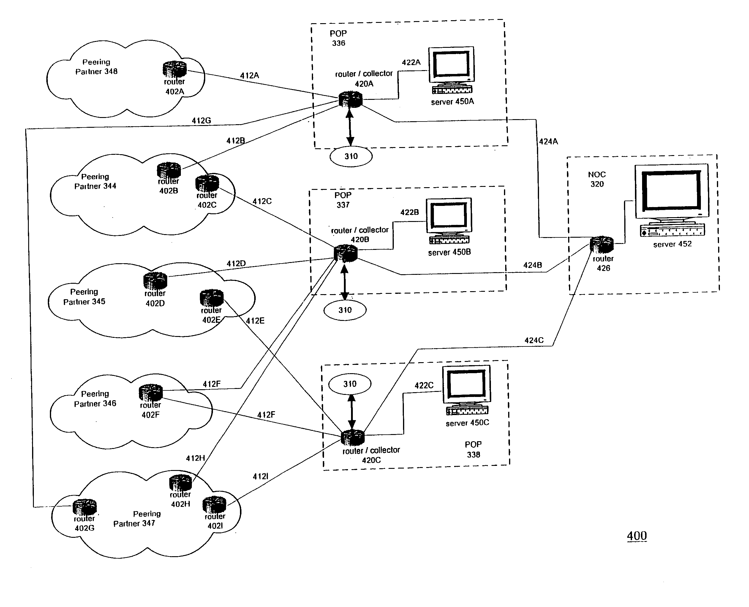
[0014] The present invention allows Web content providers and other Internet bandwidth consumers (“content providers”) to obtain the Internet bandwidth they require, while providing a system for paying access providers on a per-bit basis for the traffic they carry. The system manages and facilitates the routing of traffic within the system through the development of a topological “address space map” of the system to enable a “best route” selection process. The “topology” of the network is analogous to the geography of the network in circuit route distances. Content providers do not have to be concerned with multi-homing routing issues, and access providers are assured that they will be paid for the use of their network.
[0020] The NOC develops “best route” information, which is distributed back to the set of POPs and the interconnected peering partner networks. The “best route” information ensures that traffic is properly routed through preferred routes on the intelligent routing network, keeping traffic on the backbone when possible, and avoiding inefficient routing. The NOC also selects new routes to be injected into the intelligent routing network in order to further improve the accuracy of the address space map.

Problems solved by technology

Instead of peering, large ISPs that have a national backbone offer transit service to smaller, regional ISPs who cannot offer reciprocal backbone sharing.
These mutual agreements to exchange information traffic (bandwidth) freely and without charge do not make economic sense if one peering partner is forced to carry substantially more traffic than another.
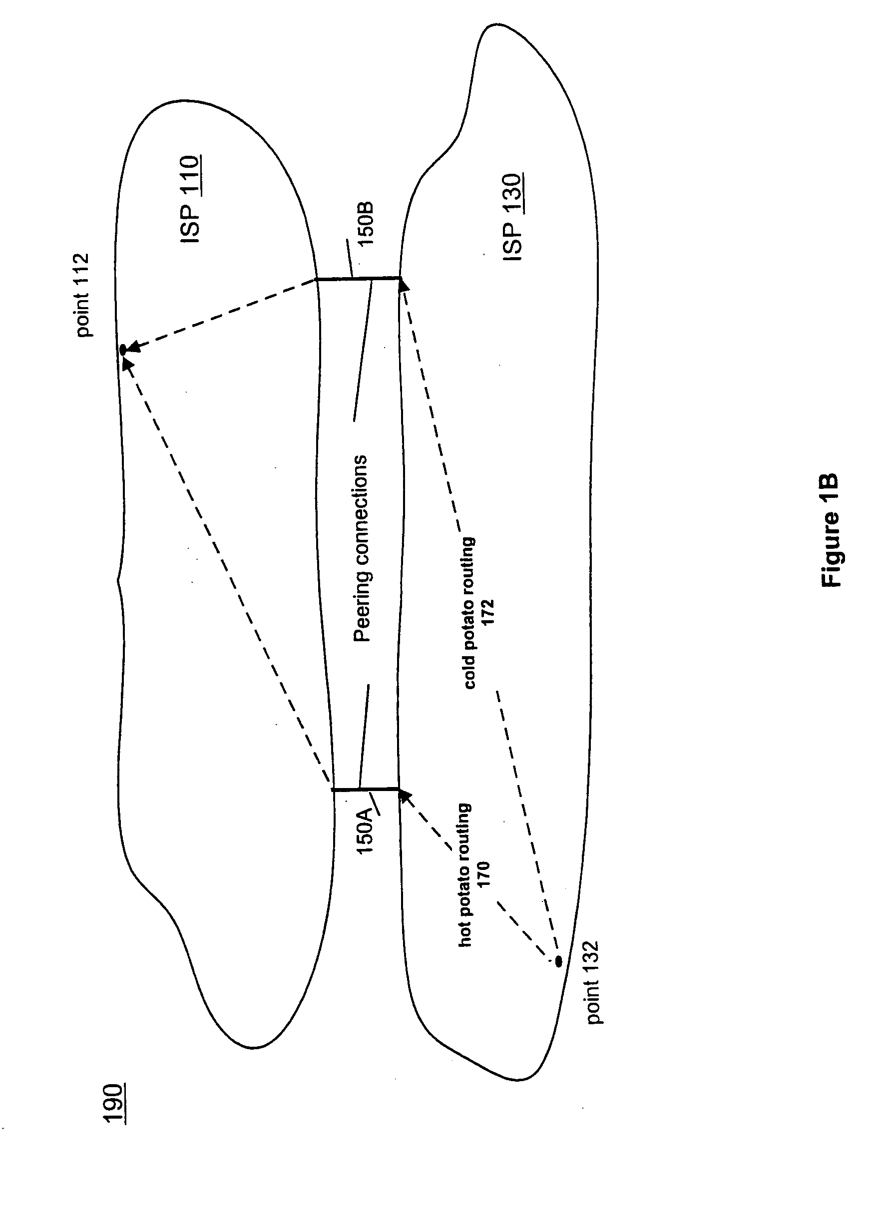
Unbalanced bandwidth may affect peering relationships because most peered data is routed between peers using a routing method called “hot potato routing.”
There is no incentive for a carrier to transport additional bandwidth if a peer network is available to carry the traffic.
However, although Internet peering models are generally based upon the assumption of symmetric bandwidth between peers, this assumption has proven to be flawed.
The growth of the WWW and increases in WWW traffic have exacerbated the problem of bandwidth asymmetry.
Web content providers tend to transmit copious amounts of data.
Bandwidth between Web content providers and the individuals who view Web content is often unbalanced.
An individual might request a Web page by sending just a single address or page request, whereas the Web page content provider returns multiple Web pages to the individual, thereby consuming large amounts of bandwidth.
Furthermore, ISP A is unable to charge its own customers more for the extra bandwidth, because the entity originating the extra bandwidth is a customer of ISP B. The current peering system does not provide the proper economic incentives for an ISP to increase its bandwidth, because the increased bandwidth may be consumed by the ISP's peers.
Web content providers are often constrained by the bandwidth limitations they experience through their ISP.
However, the addition of redundant paths to each potential client terminal results in increased complexity.
The resulting burden of best path management is a difficult task and not one that will likely be mastered by most Web content providers.
The Border Gateway Protocol (BGP) (which is used to route data between networks on the Internet) is a poor tool, with limited best path information available to the automated decision making process in the router.
However, because Web traffic contributes substantially to the peering bandwidth asymmetry problem, a method is required to compensate all network carriers for the Web bandwidth they carry, including Web traffic that originates in a network peer.

Method used


Image

  • Internet route deaggregation and route selection preferencing
  • Internet route deaggregation and route selection preferencing
  • Internet route deaggregation and route selection preferencing

Examples


Embodiment Construction

[0038] Reference will now be made in detail to several embodiments of the present invention, examples of which are illustrated in the accompanying drawings. Wherever practicable, the same reference numbers will be used throughout the drawings to refer to the same or like parts.

[0039] Introduction

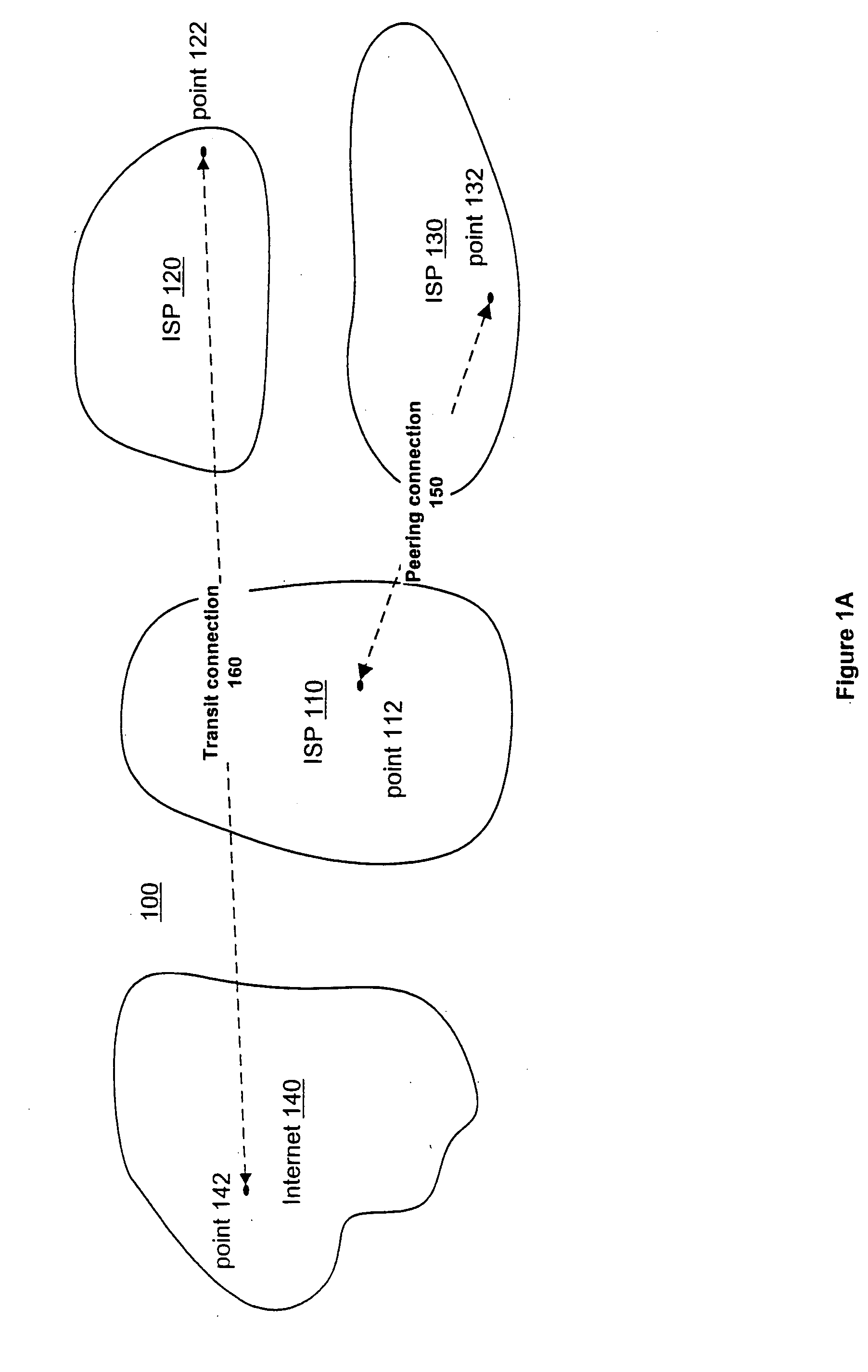
[0040]FIG. 1A provides background information on existing systems for carrying Internet and Web traffic. FIG. 1A shows a communications network 100. Network 100 includes three Internet Service Providers (ISPs) 110, 120, and 130 and a representation of the Internet 140. ISP 110 includes a point 112; ISP 120 includes a point 122; ISP 130 includes a point 132; and the Internet 140 includes a point 142. Each point represents a particular Internet Protocol (IP) address within the network 100. Each ISP represents a set of equipment and telecommunication lines providing Internet access for a certain geographic region. An ISP provides an Internet connection to various individuals and companies, wh...


PUM


Abstract

A method and system for managing the routing of traffic within a network develops a topological address space map of the network to enable a “best route” selection process. The network is comprised of a backbone connected to a plurality of peering partners. Points on the network monitor traffic flows. A central facility analyzes the traffic flows and routes within the network and performs intelligent routing management. Intelligent routing management ensures that traffic is properly routed through preferred routes on the network, and avoids inefficient routing. Intelligent routing management also selects new routes to be injected into the network in order to further improve the accuracy of the address space map of the network. Intelligent routing management ensures that bandwidth is requested and delivered topologically closely to peering partner networks, and that traffic is carried by the backbone for long haul data distribution in both directions.

Description

CROSS REFERENCE TO RELATED APPLICATION [0001] This application is a divisional application and claims the benefit of copending U.S. patent application Ser. No. 09 / 594,461, filed Jun. 14, 2000, which application is hereby incorporated by reference.BACKGROUND [0002] 1. Field of the Invention [0003] The present invention relates generally to network routing, and more particularly, to dynamically determining regional address locations for best exit routing based upon route deaggregation and route selection preferencing. [0004] 2. Background of the Invention [0005] The growth of the Internet, and the World Wide Web (WWW) in particular, has led to enormous increases in the amount of traffic flowing over the group of connected networks that comprise the Internet and connected network systems. Access providers such as Internet Service Providers (ISPs) provide connections for businesses and individuals to connect to the Internet and access the WWW. ISPs must interconnect in order to allow th...

Claims


Application Information

Patent Timeline
IPC IPC(8): H04L12/56
CPCH04L45/02Y10S707/99931H04L45/06H04L45/033
Inventor GADDIS, MICHAEL E.HICKS, PETER N.BARMANN, DAVIDNUNES, STEVEN T.
Owner LEVEL 3 COMM LLC
Learn More