
Offshore wind turbine and method for making same

a wind generator and offshore technology, applied in wind energy generation, motors, artificial islands, etc., can solve the problems of large hoisting capacity, difficult movement and installation of cranes, and difficulty in building such wind generators

Inactive Publication Date: 2004-09-02
SAIPEM SA
View PDF4 Cites 211 Cited by
  • Summary
  • Abstract
  • Description
  • Claims
  • Application Information

AI Technical Summary

Benefits of technology

[0015] Said support in the compact configuration thus facilitates manufacture, since the maximum height required for hoisting equipment is considerably reduced. It also makes it easier to transport the wind generator between a first site where the main components are assembled, which site may be located, in particular, on land or in shallow water, and a second site where the wind generator is installed in its final configuration, which site may in particular be in water deeper than that of the first site; the invention also makes it easier to erect the wind generator on the second site--where it is to produce energy--, with this being achieved by causing the moving portions of the support to move relative to each other in such a manner as to convert the support from its compact position to its deployed position.
[0017] Also preferably, each of said support portions is of elongate shape, said portions being movable in translation by sliding relative to each other so as to obtain a deployable support that is simple to manufacture.
[0024] Alternatively, or in addition to said passive hydraulic thrust means (buoyancy thrust), said thrust means may comprise means for introducing a driving fluid (or slurry) under pressure into said cavity, together with sealing means for preventing or restricting leakage of said driving fluid passing through the residual annular space that exists between the inside face of the wall of said first body and the outside face of the wall of said second body. This makes it possible to use the first body as the cylinder of an actuator and to use a fraction of said second body as the piston of said actuator. The pressure exerted by said driving fluid present in said cavity against the walls of said second body causes the second body to slide inside the first body and thus enables said pylon or support to be deployed.

Problems solved by technology

The mass of such a generator can reach or exceed 100 metric tonnes (t) or 200 t. The height of a pylon supporting such a generator can be about 50 meters (m) to 100 m, and the mass of the pylon can lie in the range 100 t to 500 t. It will thus be understood that constructing such wind generators presents difficulties.
Installing large-capacity wind generators on land requires cranes to possess very long jibs, and considerable hoisting capacity.
Such cranes are difficult to move and set up, and in particular in order to comply with road clearance regulations they need to be disassembled into a plurality of elements.
By way of example, a 350 t crane having a 90 m jib requires nine vehicles, four of which constitute exceptional loads; in addition, setting up the crane takes several days, and taking it down again requires as many.
Installing a wind generator whose base or foundation is immersed in shallow water--less than 10 m of water--presents additional difficulties, particularly when the installation site is several kilometers from the coast line; it is possible under such circumstances to use hoisting equipment of the kind commonly used on land, which is taken to the installation site and placed temporarily on structures themselves resting on the bottom of the water.
Installing a wind generator in deep water presents additional difficulties, even though pontoon cranes presenting considerable load capacity can be used for installation purposes.
However, such pontoon cranes need to be capable of operating in the open sea, which considerably reduces the amount of equipment available and generally requires a pontoon crane to be taken from somewhere very distant from the installation site, leading to costs that are unacceptable for project profitability.
In addition, such pontoon cranes are generally booked a long time in advance for developing off-shore oil fields, since the critical stages of installation are generally concentrated exclusively in periods of fair weather, i.e. periods when it would also be desirable to be installing off-shore wind generators.

Method used


Image

  • Offshore wind turbine and method for making same
  • Offshore wind turbine and method for making same
  • Offshore wind turbine and method for making same

Examples


Embodiment Construction

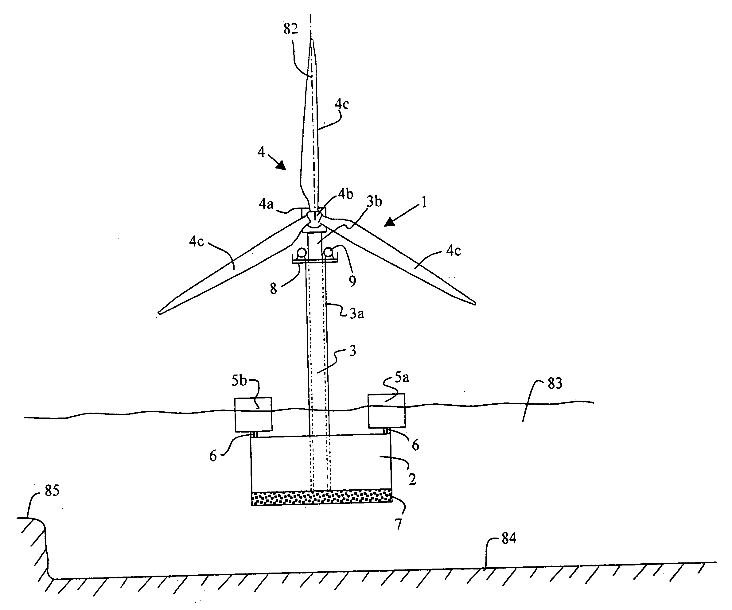
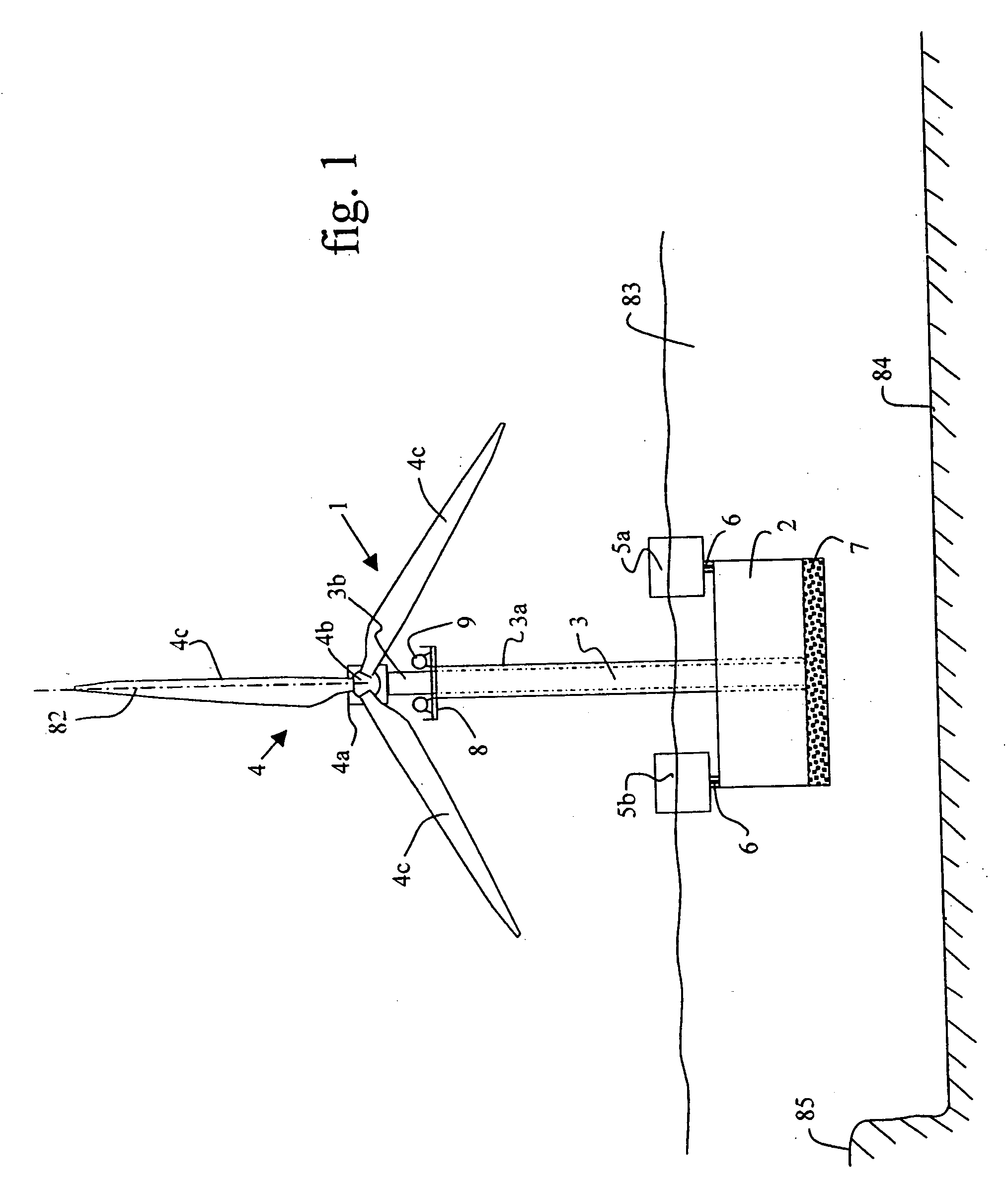
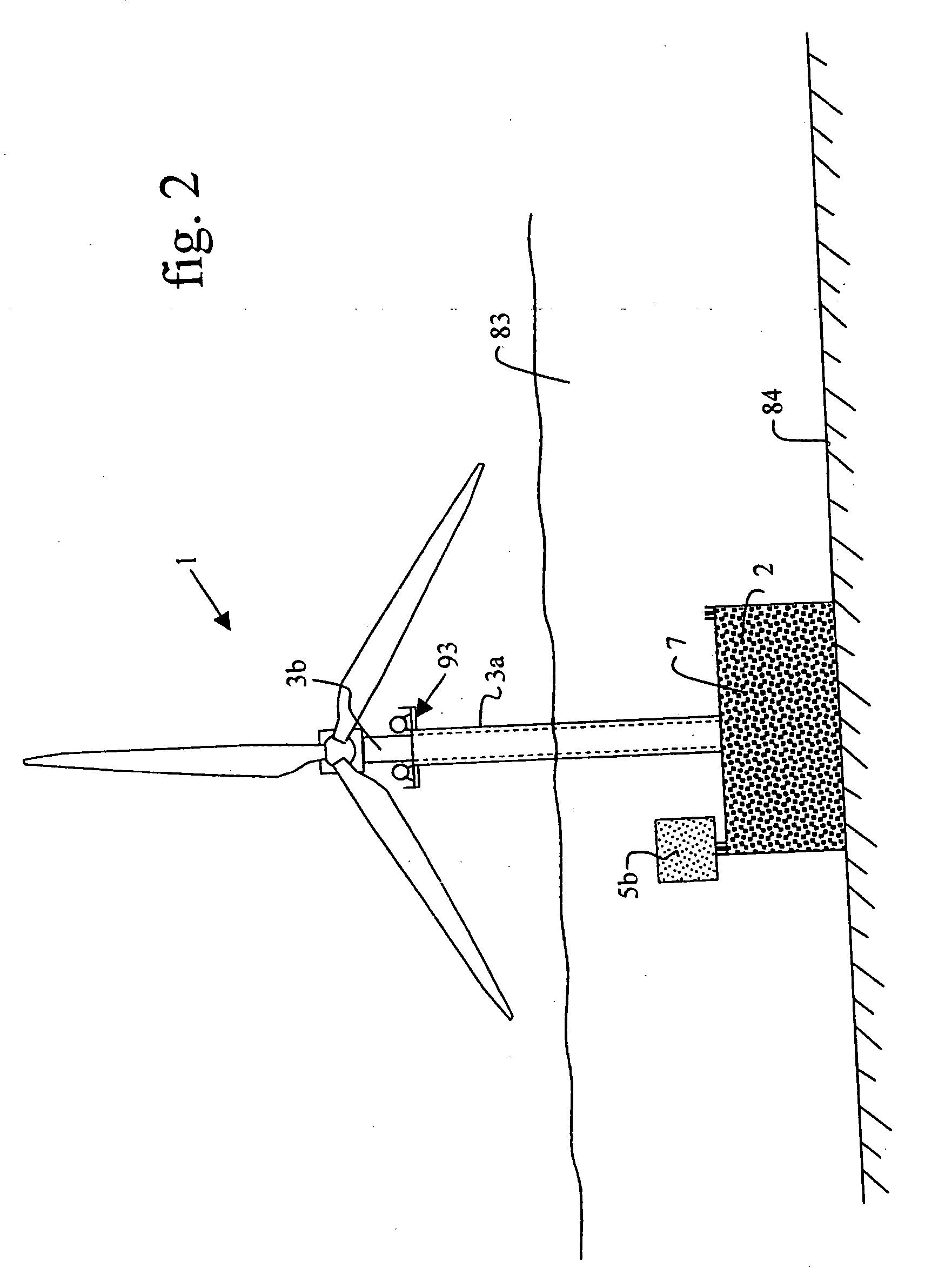
[0051] FIGS. 1 to 4 are side views of an off-shore wind generator 1 while it is being put into place, the wind generator comprising a base 2 and a pylon 3 constituted by a bottom portion 3a received in said base, and a top portion 3b of outside diameter 80 smaller than the inside diameter 81 (FIG. 4) of the bottom portion 3a. The two tubular portions 3a and 3b of the pylon can slide along their substantially vertical common longitudinal axis 82 by means of a guide system similar to that shown in FIGS. 5 and 6. The telescopic pylon is shown in its retracted position in FIGS. 1, 2, and 8. At the top of the top portion 3b of the pylon, there is installed the active portion 4 of the wind generator comprising an electricity generator 4a secured to a wind turbine constituted by a shaft 4b that is rotatable about a horizontal axis and that supports three blades 4c.

[0052] Stability of the wind generator while it is being towed at sea and put into place on its production site constitutes the...


PUM


Abstract

The present invention relates to wind generators installed off-shore, in particular at sea, to support structures forming a part of such wind generators, and to methods of making and installing such wind generators. The technical field of the invention is that of making, transporting, and installing wind generators for producing electricity, more particularly off-shore, and in large numbers, so as to form wind "farms". The wind generator of the invention comprises a wind turbine and a deployable telescopic pylon or support supporting the turbine, and a gravity base supporting the pylon or support.

Description

[0001] The present invention relates to wind generators installed off-shore, in particular at sea, to support structures forming parts of such wind generators, and to methods of manufacturing and installing such wind generators.[0002] The technical field of the invention is that of manufacturing, transporting, and installing wind generators for producing electricity, more particularly very large capacity off-shore wind generators for installing at sea, more particularly away from coasts and in very large numbers, in order to form wind farms.[0003] Whereas land-based wind turbines have been constructed for several centuries, constructing wind generators at sea is much more recent.[0004] A modern wind generator, whether on land or at sea, generally comprises a turbine having a plurality of blades and a horizontal axis, together with an electricity generator coupled to the turbine, both of them being supported at the top end of a vertically elongate support such as a mast or a pylon.[0...

Claims


Application Information

Patent Timeline
IPC IPC(8): F03D1/00F03D13/10F03D13/20F03D13/25
CPCE02B2017/0086Y02E10/728E02D27/42F03D1/001F03D11/04F03D11/045F05B2230/60F05B2230/61F05B2240/9151F05B2240/916F05B2240/93F05B2240/95Y02E10/721Y02E10/727E02B2017/0091E02D27/425F03D13/10F03D13/22F03D13/25Y02E10/72Y02P70/50
Inventor RUER, JACQUESCOCHE, EDMONDGREGOIRE, JEAN-PAULPORTENSEIGNE, CHRISTOPHEROCHER, XAVIER
Owner SAIPEM SA
Learn More