
Method of coating a substrate with a particle stabilized foam

a technology of particle stabilized foam and substrate, which is applied in the direction of physical/chemical process catalysts, organic compound/hydride/coordination complex catalysts, separation processes, etc., can solve the problems of not divulging or teaching any coating application, and achieve excellent control

Active Publication Date: 2017-10-26
JOHNSON MATTHEY PLC
View PDF2 Cites 7 Cited by
  • Summary
  • Abstract
  • Description
  • Claims
  • Application Information

AI Technical Summary

Benefits of technology

The invention is about a new method for coating substrates with a particle stabilized foam to control emissions in exhaust systems. This new method has certain advantages over traditional coating methods. The foam coating provides better control over short-depth dose coating and can even be applied to the substrate. It also reduces back pressure and allows for the passage of exhaust gas through the foam layer, where the pores can help collect soot. The high specific surface area and rough surface of the foam layer improves the activity of the emissions control device. Increased backpressure can be a problem in emissions control devices, but the new method helps avoid this issue. Overall, this new method addresses the challenges of controlling emissions in exhaust systems and improves the performance of emissions control devices.

Problems solved by technology

Problems can arise during the coating process that can depend on the properties of the substrate that is to be coated (e.g. size of the channels, the material from which the substrate is made and its porosity) and the properties (e.g. rheology) of the liquid that is used to form the coating.
However, WO 2007 / 068127 A1 does not disclose or teach any coating applications.

Method used


Image

  • Method of coating a substrate with a particle stabilized foam
  • Method of coating a substrate with a particle stabilized foam
  • Method of coating a substrate with a particle stabilized foam

Examples


example 1

[0238]A gamma-alumina suspension was prepared by mixing the appropriate amount of powder with water. The pH was adjusted to 5.5 with HNO3 and the suspension stirred to homogenize. The suspension was milled to a d50 of <6 microns.

[0239]To a portion of this suspension, valeric acid (1.6% of the mass of Alumina) was added and the pH adjusted to 4.8, with NH3. Air was introduced into the suspension using a Kenwood Chef Classic™ food mixer with a whisk attachment, stirring at maximum speed for 10 minutes to produce a foam with 5.9 times the volume of the starting suspension.

[0240]The foam was aged for three days during which no liquid drainage, drying or coarsening of the bubble structure was observed.

example 2

[0241]Boehmite powder (an alumina supplied by Sasol) was added to demineralised water. This suspension was stirred for three hours. A Cu exchanged small pore zeolite with the CHA structure and SAR 25 (3.0 wt. % Cu) was added slowly (Zeolite:Boehmite ratio 9:1). The total solids content of this suspension was 31 wt %.

[0242]To a portion of this suspension, valeric acid (of varying quantities described in Table 1) was added and the pH adjusted, when needed, to 4.8 with NH3 Air was introduced into each portion of the suspension using a Kenwood Chef Classic™ food mixer with a whisk attachment, stirring at maximum speed for 10 minutes to produce a foam.

TABLE 1Foam Samples Summary of EXAMPLE 2SampleValeric AcidInitial VolumeFoam VolumeIDSolids wt. %mmol / g solids(ml)(ml)A19.970.085150300B19.970.1801501200C18.840.173150200D31.000.1091501200E29.950.0561501100F31.390.082100700G30.670.2101501200H19.820.1221501100I20.150.2741501250J20.340.2881501200

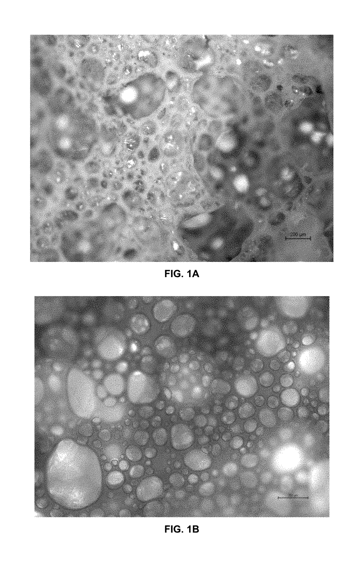
[0243]FIG. 1a shows fresh foam optical microsco...

example 3

SCR Foam Coating Test

[0244]A suspension was prepared by diluting and then stirring a suspension of similar composition to the one in EXAMPLE 2 until it became homogeneous.

[0245]To a portion of this suspension, valeric acid (2.1% of the mass of solid component) was added and the pH adjusted to 4.8 with of tetra-n-propyl-ammonium hydroxide. Air was introduced into the suspension using a Kenwood Chef Classic™ food mixer with a whisk attachment, stirring at maximum speed for 10 minutes to produce a foam.

[0246]The foam was introduced to the outlet end of a 1 inch core taken from a cordierite flow-through substrate using a vacuum applied from the inlet end. The core was dried and then calcined at 500° C. for 2 h.

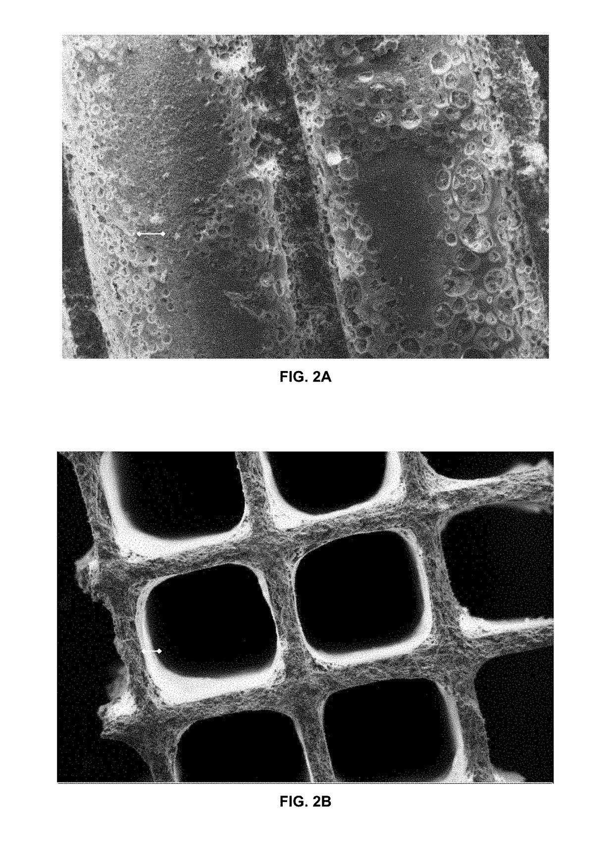
[0247]As shown in FIG. 2, scanning electron microscopy of the coated core indicates that the solid foam coating forms a uniform layer on the cell walls. Open bubbles are visible at the surface of the solid foam layer. The images were taken in the following conditions: 2a) accelera...


PUM

PropertyMeasurementUnit
median particle sizeaaaaaaaaaa
diameteraaaaaaaaaa
median pore diameteraaaaaaaaaa

Abstract

A method of coating a substrate with a foam is described. The method comprises:(a) introducing a foam into a substrate comprising a plurality of channels through open ends of the channels at a first end of the substrate; and(b) applying at least one of (i) a vacuum to open ends of the channels at a second end of the substrate and (ii) a pressure to the open ends of the channels at the first end of the substrate;wherein the foam comprises a particulate material, and wherein the foam is particle stabilized.

Description

CROSS REFERENCE TO RELATED APPLICATIONS[0001]This application claims priority benefit to Great Britain Patent Application No. 1606133.5 filed on Apr. 11, 2016, which is incorporated herein by reference.FIELD OF THE INVENTION[0002]The invention relates to a method of coating a substrate with a particle stabilized foam. The coated substrate is for use in an emissions control device for treating or removing pollutants from an exhaust gas produced by an internal combustion engine. The invention further relates to an emissions control device comprising a substrate and a solid foam layer, and to uses of the emissions control device.BACKGROUND TO THE INVENTION[0003]Emissions control devices (e.g. catalysts, such as three-way catalysts or diesel oxidation catalysts) for treating the exhaust gas of an internal combustion engine in both mobile and stationary applications typically include a substrate (e.g. a honeycomb monolith substrate) coated with a liquid that comprises a catalyst componen...

Claims


Application Information

Patent Timeline
Patent Type & Authority Applications(United States)
IPC IPC(8): B01J29/76F01N3/28B01D53/94B01J21/04B01J35/02B01J35/04B01J37/08B01J37/02B01J35/10F01N3/20B01J35/00
CPCB01J29/763F01N2370/04B01J35/0006B01J35/04B01J35/026B01J35/1076B01J37/0215B01J37/0236B01J37/08B01D53/9418F01N3/2066F01N3/2803B01D2255/2092B01D2255/20761B01D2255/50F01N2250/02F01N2330/22F01N2330/06B01J21/04F01N3/106F01N3/2828F01N3/035F01N2330/00F01N13/009B01J23/42Y02T10/12B01J35/30B01J35/56B32B5/16B32B5/18F01N3/24F01N3/28B32B3/12B01D53/94B01J21/00B01J23/00B01J25/00B01J27/00B01J29/00B01J31/00B01J35/00B01J37/02B32B3/26B32B3/30F01N3/022B01D53/92B01J29/72F01N3/10B01J35/60B05D7/22B01J35/19B01J35/50B01J35/657
Inventor BERNADINI, CECILIACAMPBELL, THOMASCHANDLER, GUY RICHARDDALY, CHRISTOPHERHARDSTONE, KATHARINE ANNHOTCHKISS, THOMASTHOMPSETT, DAVID
Owner JOHNSON MATTHEY PLC
Learn More