
Spiral membrane element

a membrane element and spiral technology, applied in the field of spiral membrane elements, can solve the problems of difficult to ensure water resources in a stable manner, and achieve the effects of increasing the effective membrane area, ensuring water resources stability, and increasing the permeation flow ra

Active Publication Date: 2017-10-26
NITTO DENKO CORP
View PDF2 Cites 6 Cited by
  • Summary
  • Abstract
  • Description
  • Claims
  • Application Information

AI Technical Summary

Benefits of technology

The invention provides a new design for a spiral membrane element that allows for an increased effective membrane area while reducing the likelihood of deformation-induced decreases in rejection. This is achieved by using a specific tricot knit fabric as a permeation-side flow path material, even when a composite semi-permeable membrane is thinner than conventional.

Problems solved by technology

In recent years, an attempt to desalinate seawater has been made in the coastal big cities in arid or semi-arid areas where it is difficult to ensure water resources in a stable manner.

Method used


Image

  • Spiral membrane element
  • Spiral membrane element
  • Spiral membrane element

Examples


production example 1 (

Production of Composite Semi-Permeable Membrane)

[0073]A long porous support (90 μm thick) was prepared by a process including continuously applying a solution of a mixture of polysulfone and dimethylformamide (polymer concentration 18.35% by weight) to the surface of a 65-μm-thick commercially available polyester nonwoven cloth (about 1 m wide) for a water treatment membrane support, while feeding the cloth, and then subjecting the applied solution to a coagulation treatment in water at 35° C. to form a 25-μm-thick polymer porous layer.

[0074]A solution A containing a mixture of 3.6% by weight of piperazine hexahydrate and 0.15% by weight of sodium lauryl sulfate was brought into contact with the surface of the polymer porous layer of the porous support, while the porous support was fed, and then the excess solution A was removed, so that a solution A coating layer was formed. Subsequently, a solution B containing 0.4% by weight of trimesic acid chloride in a hexane solvent was broug...

production example 2 (

Production of Composite Semi-Permeable Membrane)

[0075]A long composite semi-permeable membrane was produced under the same conditions as those in Production Example 1, except that the nonwoven cloth used had a thickness of 90 μm, the polymer porous layer was formed with a thickness of 40 μm, and the porous support obtained had a thickness of 130 μm.

examples 1 to 5

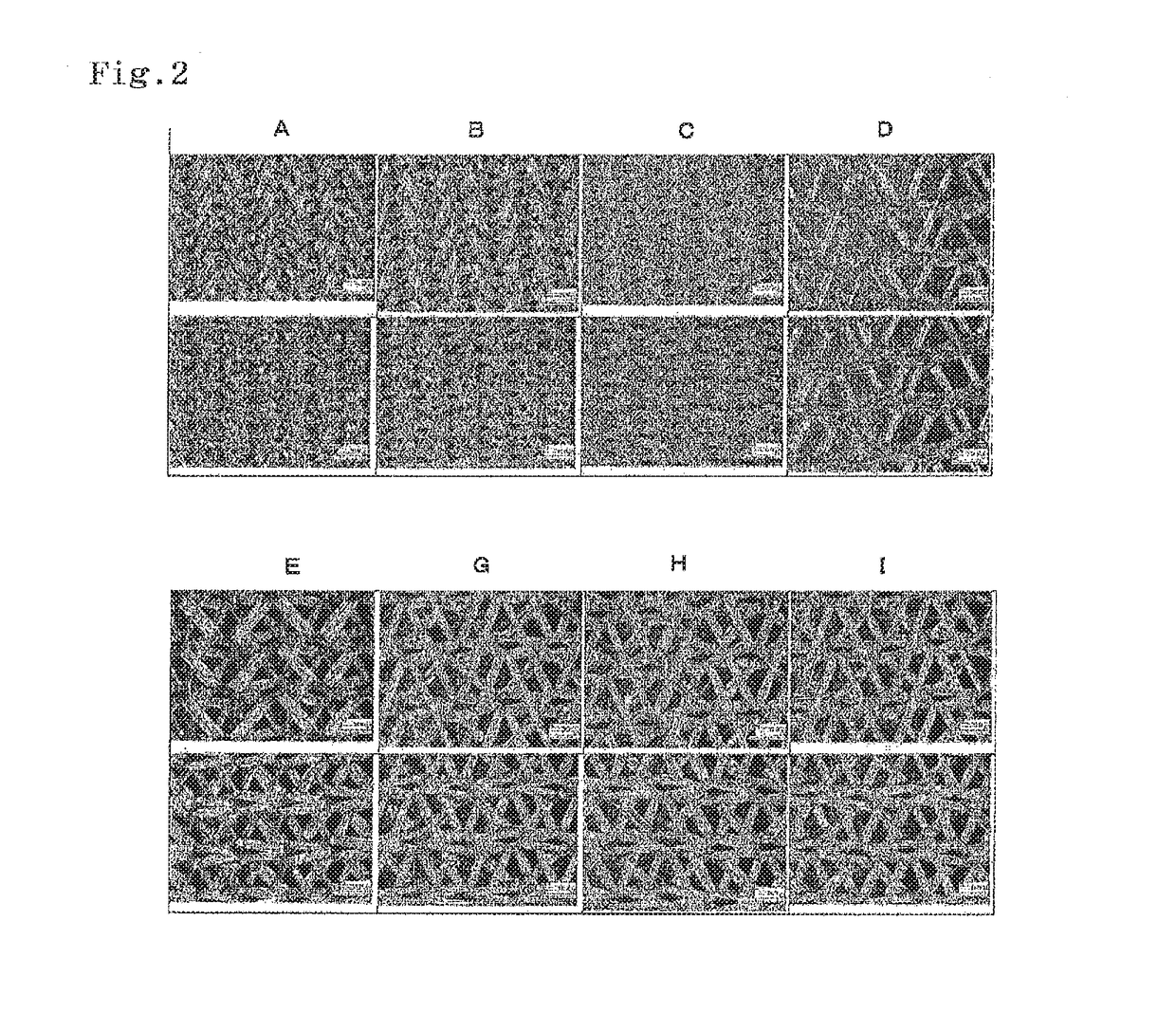
[0076]The permeate flux and the rejection were evaluated by the above method using the permeation-side flow path materials A to E shown in Table 1 and FIG. 2 and the composite semi-permeable membrane obtained in Production Example 1. The results are also shown in Table 1. The results are further graphed and shown in FIGS. 3 and 4.


PUM


Abstract

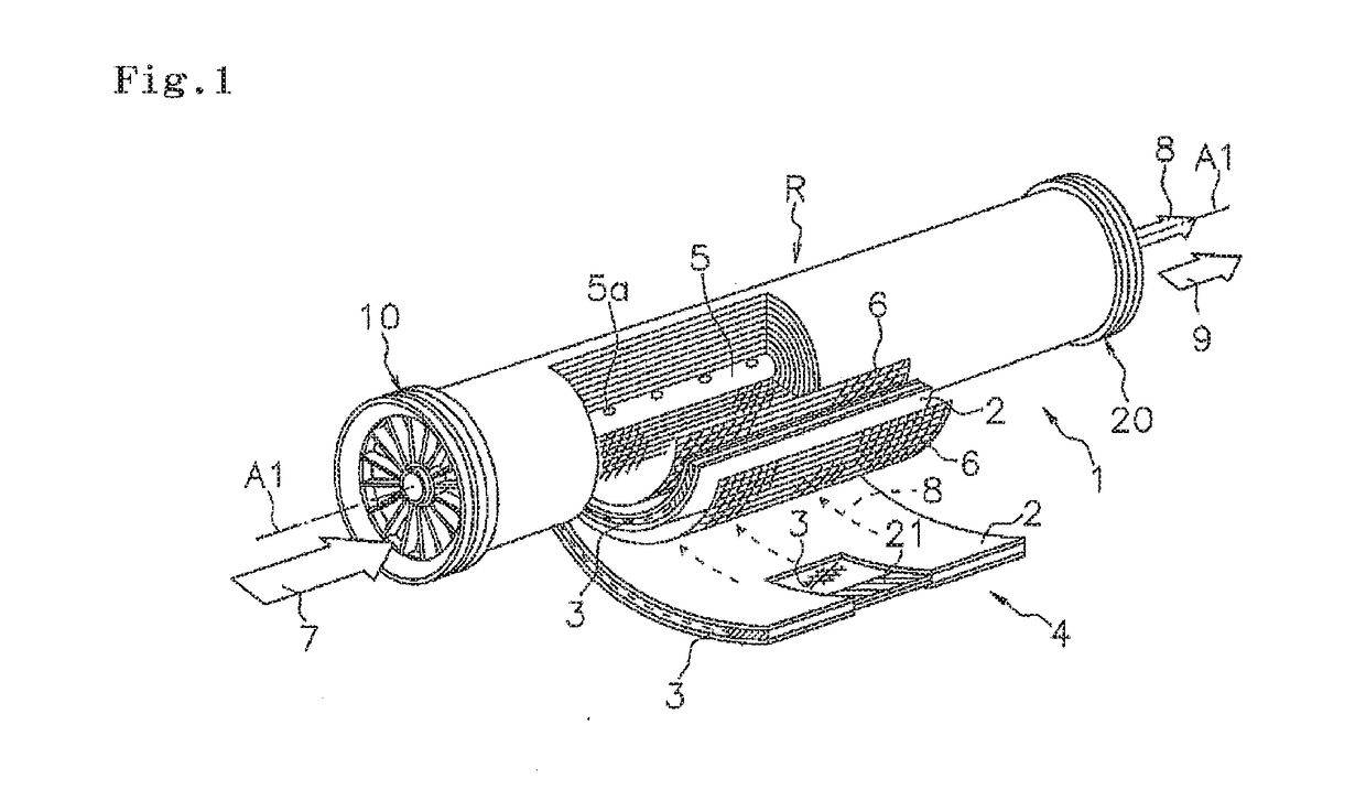
The present invention provides a spiral membrane element in which the effective membrane area of a composite semi-permeable membrane can be increased and any decrease in rejection rate is less likely to occur. The spiral membrane element includes: a laminate including a permeation-side flow path material, a supply-side flow path material, and a composite semi-permeable membrane having a separation function layer on a surface of a porous support; a perforated central tube around which the laminate is wound; and a sealing member for preventing mixing between the supply-side flow path and a permeation-side flow path, the spiral membrane element being characterized in that the thickness of the porous support of the composite semi-permeable membrane is 80 μm to 100 μm, the permeation-side flow path material is formed from a tricot knit fabric, and the width of a groove that continues in a straight line is 0.05 mm to 0.40 mm.

Description

TECHNICAL FIELD[0001]The invention relates to a spiral membrane element (hereinafter also abbreviated as a “membrane element”) having a composite semi-permeable membrane for separating and / or concentrating specific substances from a variety of liquids.BACKGROUND ART[0002]In recent years, an attempt to desalinate seawater has been made in the coastal big cities in arid or semi-arid areas where it is difficult to ensure water resources in a stable manner. Further, in areas poor in water resources such as China and Singapore, an attempt to purify industrial wastewater and domestic wastewater has been made for reusing the water. More recently, reuse of wastewater discharged from oilfield plants or the like has also been attempted by removing oils and salts from the oil-contaminated wastewater having high turbidity. A membrane method using a composite semi-permeable membrane has been found to be effective for such water treatment in terms of cost and efficiency.[0003]Such water treatment...

Claims


Application Information

Patent Timeline
IPC IPC(8): B01D63/10B01D69/10
CPCB01D63/10B01D2325/04B01D69/10B01D63/103B01D2313/146Y02A20/131B01D67/00042B01D69/107B01D69/1071B01D69/1213B01D63/101
Inventor YAMAGUCHI, TAISUKEMIZUIKE, ATSUKOECHIZEN, MASASHIMATSUI, KAZUSA
Owner NITTO DENKO CORP
Learn More