3D printers and feedstocks for 3D printers
a 3d printer and 3d printing technology, applied in the direction of additive manufacturing processes, manufacturing tools, transportation and packaging, etc., can solve the problems of difficult or impossible to manufacture highly customized complex parts and products using traditional technologies, negatively affecting the properties of composite objects, and poorly suited to high-volume, low-cost production. achieve the effect of facilitating the dispersion of carbon compounds
- Summary
- Abstract
- Description
- Claims
- Application Information
AI Technical Summary
Benefits of technology
Problems solved by technology
Method used
Image

Examples
example 1
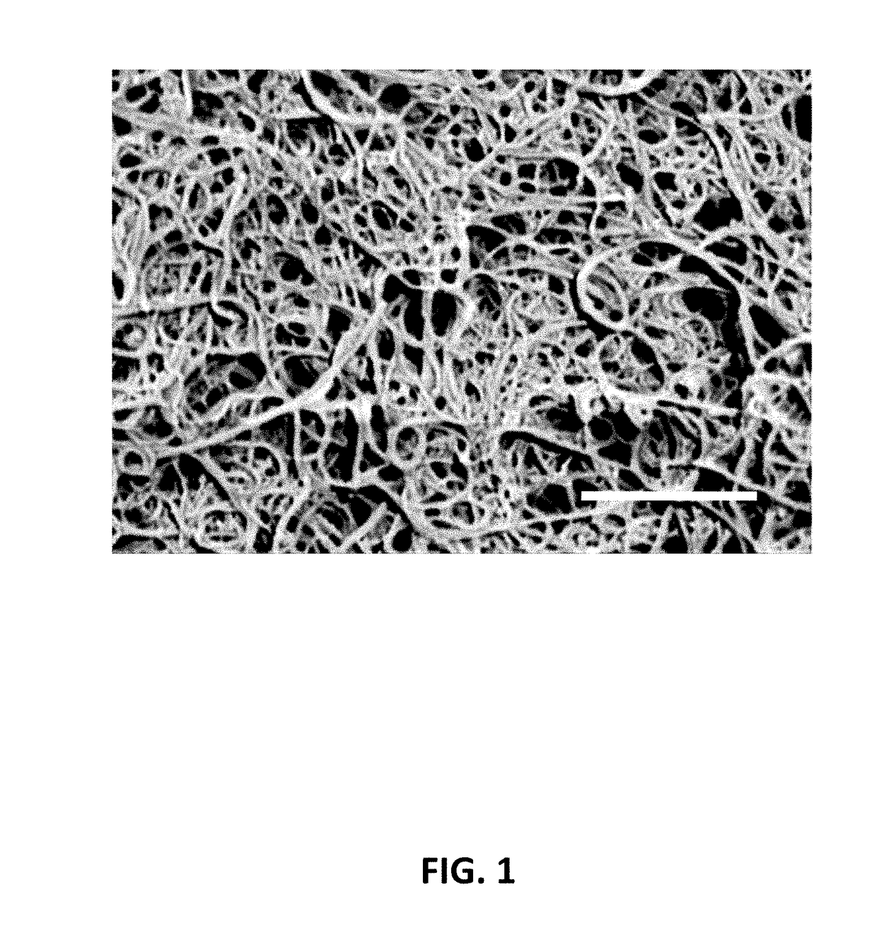
[0154]As-synthesized multi-wall CNT material (comprising about 85 wt % inorganic impurities) was refluxed in excess amount of about 1M HCl for about 5 hours, and then filtered to remove the main volume of the acid while keeping the CNT material wet. The purified product (comprising about 2 wt % inorganic impurities) was washed two times with de-ionized water to remove the residual acid, and then separated into three parts for the experiments described in other Examples. The first part was dried in a convection oven at about 120° C. for about 4 hours. The second part was kept wet and refluxed in water (at CNT concentration of about 2 g / L) for about 5 hours to loosen up the CNTs. The third part was washed with copious amounts of toluene three times thereby substantially replacing the water with toluene as a solvent and bringing the CNT concentration to about 2 g / L. Then, the CNT-toluene suspension was refluxed for about 5 hours. Finally, both these CNT suspensions (one in water and on...
example 2
[0155]Dried powder of purified multi-wall CNT material prepared in Example 1 as the first part was dispersed following exactly the same process as the other two parts. To produce a stable CNT suspension, the dry powder was first refluxed in water at CNT concentration of about 2 g / L for about 5 hours, then passed 2 times through the Microfluidizer. The G / D ratio for the multi-wall CNT dry powder material as measured with about 532 nm laser excitation may vary in the range of 1.1 to 1.4. After dispersing, the G / D ratio decreased to a level varying in the range of 0.4 to 0.8 indicating increased concentration of CNT defects.
[0156]The multi-wall CNT material may be provided, for example, by Thomas Swan & Co Ltd (UK), Nanocyl (Belgium), or many other suppliers. The step of Microfluidizer treatment may be combined or substituted with any high shear mixing, sonication, wet ball milling, another similar treatment, or a combination thereof. Similar simple and efficient process may be designe...
example 3
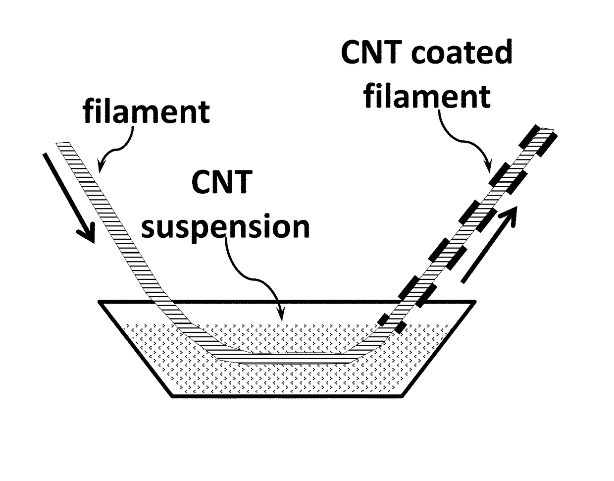
[0163]Iron powder granules (average diameter about 50 micrometers) were immersed into the aqueous CNT suspension of Example 1, agitated for about 2 hours with a magnetic stirrer at 1,000 rpm, then allowed to dry in a convection oven at about 120° C. for about 4 hours. Weight uptake by the granules yielded the amount of attached CNT of about 0.06 wt %. Examination under microscope has shown the average CNT coating thickness of 5 micrometers. The CNT-coated iron granules may be used as a feedstock for SLS, SLM, and related type 3D printers.
PUM
| Property | Measurement | Unit |
|---|---|---|
| Temperature | aaaaa | aaaaa |
| Fraction | aaaaa | aaaaa |
| Fraction | aaaaa | aaaaa |
Abstract
Description
Claims
Application Information
 - R&D
- Intellectual Property
- Life Sciences
- Materials
- Tech Scout
- Unparalleled Data Quality
- Higher Quality Content
- 60% Fewer Hallucinations
Browse by: Latest US Patents, China's latest patents, Technical Efficacy Thesaurus, Application Domain, Technology Topic, Popular Technical Reports.
© 2025 PatSnap. All rights reserved.Legal|Privacy policy|Modern Slavery Act Transparency Statement|Sitemap|About US| Contact US: help@patsnap.com