
Mass spectrometer

Active Publication Date: 2017-10-05
SHIMADZU CORP
View PDF0 Cites 11 Cited by
  • Summary
  • Abstract
  • Description
  • Claims
  • Application Information

AI Technical Summary

Benefits of technology

The mass spectrometer described in this patent improves the speed and accuracy of ion detection by changing the voltage applied to the ion source or other devices in a stepwise manner within a predetermined measurement time range. This allows the voltage to quickly stabilize at the next level, reducing the time needed for the system to become stable. This results in increased sensitivity and efficiency in detecting ions, particularly in the SIM or MRM measurement. Additionally, by reducing the cycle time and shortening the sampling period, the peak area can be more accurately determined, improving the accuracy of quantitative determination based on the peak area.

Problems solved by technology

Conventionally, it has not been a common practice to finely control the value itself of the voltage applied to the nozzle in an ESI ion source.
However, attempting to change the value of the voltage applied to the nozzle for such a change of the MRM transition causes the following problem:
However, when the output voltage is decreased without changing its polarity, the switch circuit does not work, so that the voltage requires time to change.

Method used


Image

  • Mass spectrometer
  • Mass spectrometer
  • Mass spectrometer

Examples


Embodiment Construction

[0036]A tandem quadrupole mass spectrometer as one embodiment of the present invention is hereinafter described with reference to the attached drawings.

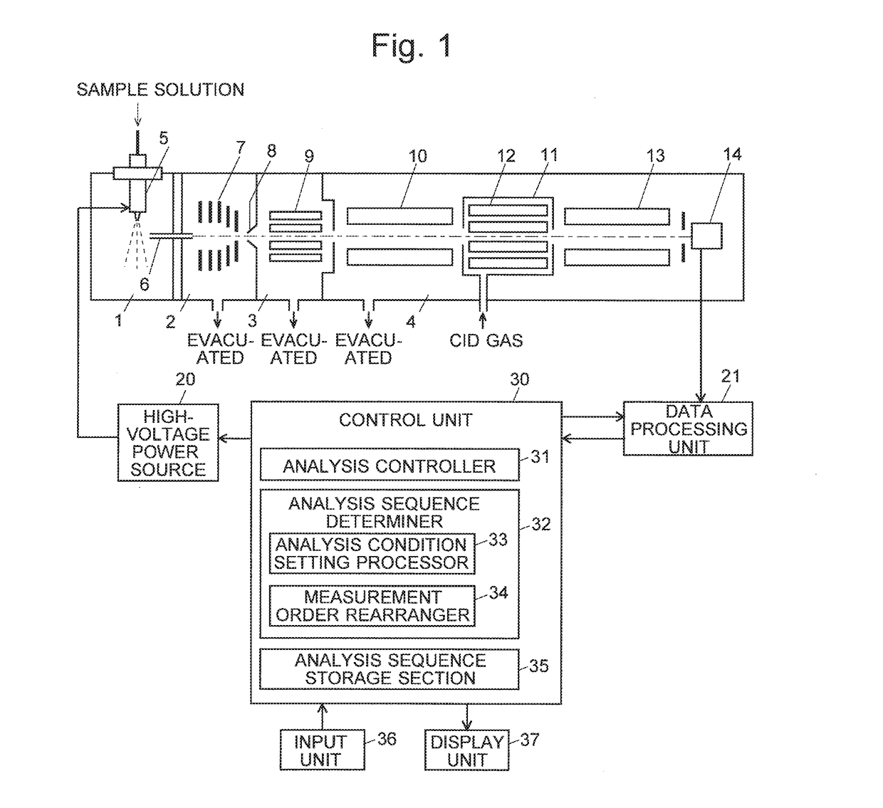
[0037]FIG. 1 is a configuration diagram showing the main components of the tandem quadrupole mass spectrometer of the present embodiment.

[0038]The tandem quadrupole mass spectrometer of the present embodiment has the configuration of a multi-stage differential pumping system including an ionization chamber 1 maintained at approximately atmospheric pressure and an analysis chamber 4 evacuated to a high degree of vacuum by a high-performance vacuum pump (not shown), between Which first and second intermediate vacuum chambers 2 and 3 are provided having their degrees of vacuum increased in a stepwise manner. The ionization chamber 1 contains an ESI probe 5 constituting an ESI ion source which is continuously supplied with a sample solution eluted from the exit port of the column of an LC (not shown). A high voltage is applied from a hig...


PUM


Abstract

In a mass spectrometer according to the present invention, when MRM measurements for a plurality of MRM transitions need to be performed within one cycle, a measurement order rearranger determines an analysis sequence by sorting the measurement in ascending order of the absolute value of an optimum application voltage (an application voltage which gives the highest ionization efficiency) to the nozzle of the ESI probe. An analysis controller performs the analysis by controlling the high-voltage power source and other relevant units according to the determined analysis sequence. Since the voltage applied to the nozzle within one cycle has no period in which the voltage is changed in the decreasing direction with the same polarity, the cycle time becomes shorter than in a conventional device.

Description

TECHNICAL FIELD[0001]The present invention relates to a mass spectrometer, and more specifically, to a mass spectrometer having a polarity-switchable high-voltage power supply device for applying, to an ion source or the like, a high voltage whose polarity depends on the polarity of an ion to be analyzed.BACKGROUND ART[0002]In a liquid chromatograph mass spectrometer (LC-MS) using a mass spectrometer as the detector for a liquid chromatograph (LC), an ion source which employs an atmospheric pressure ionization method, such as an electrospray ionization (ESI) or atmospheric pressure chemical ionization (APCI), is used in order to ionize a liquid sample eluted from a column of the LC while gasifying the same sample. For example, in an ESI ion source, a high voltage (e.g. ±several kV) having the same polarity as the ion to be analyzed needs to be applied to the tip of the nozzle from which the liquid sample is sprayed.[0003]In such a mass spectrometer, when the detection of a positive ...

Claims


Application Information

Patent Timeline
IPC IPC(8): H01J49/16H01J49/42
CPCH01J49/42H01J49/167H01J49/0031H01J49/0095H01J49/165
Inventor ASANO, NATSUYO
Owner SHIMADZU CORP
Learn More