
Electronic component and manufacturing method therefor

Active Publication Date: 2017-09-21
MURATA MFG CO LTD
View PDF3 Cites 3 Cited by
  • Summary
  • Abstract
  • Description
  • Claims
  • Application Information

AI Technical Summary

Benefits of technology

The present invention relates to an electronic component with improved heat dissipation and stability. The component has a heat-dissipation accelerating member and a sealing resin layer that contact each other, allowing for better physical stability and effective heat dissipation. A shielding member is formed to cover the external area of the sealing resin layer, providing better electromagnetic shielding and improving heat dissipation. The technical effects of this invention include improved performance and reliability of electronic components.

Problems solved by technology

Thus, heat dissipation from the electronic component element is not sufficiently performed other than in the contact area between the conductive post and the electronic component element.

Method used


Image

  • Electronic component and manufacturing method therefor
  • Electronic component and manufacturing method therefor
  • Electronic component and manufacturing method therefor

Examples


Embodiment Construction

[0056]The present invention will be described below in detail with reference to the drawings and specific preferred embodiments of the present invention.

[0057]The preferred embodiments disclosed in this specification are only examples, and the configuration in one preferred embodiment may partially be replaced by or combined with the configuration in another preferred embodiment, for example.

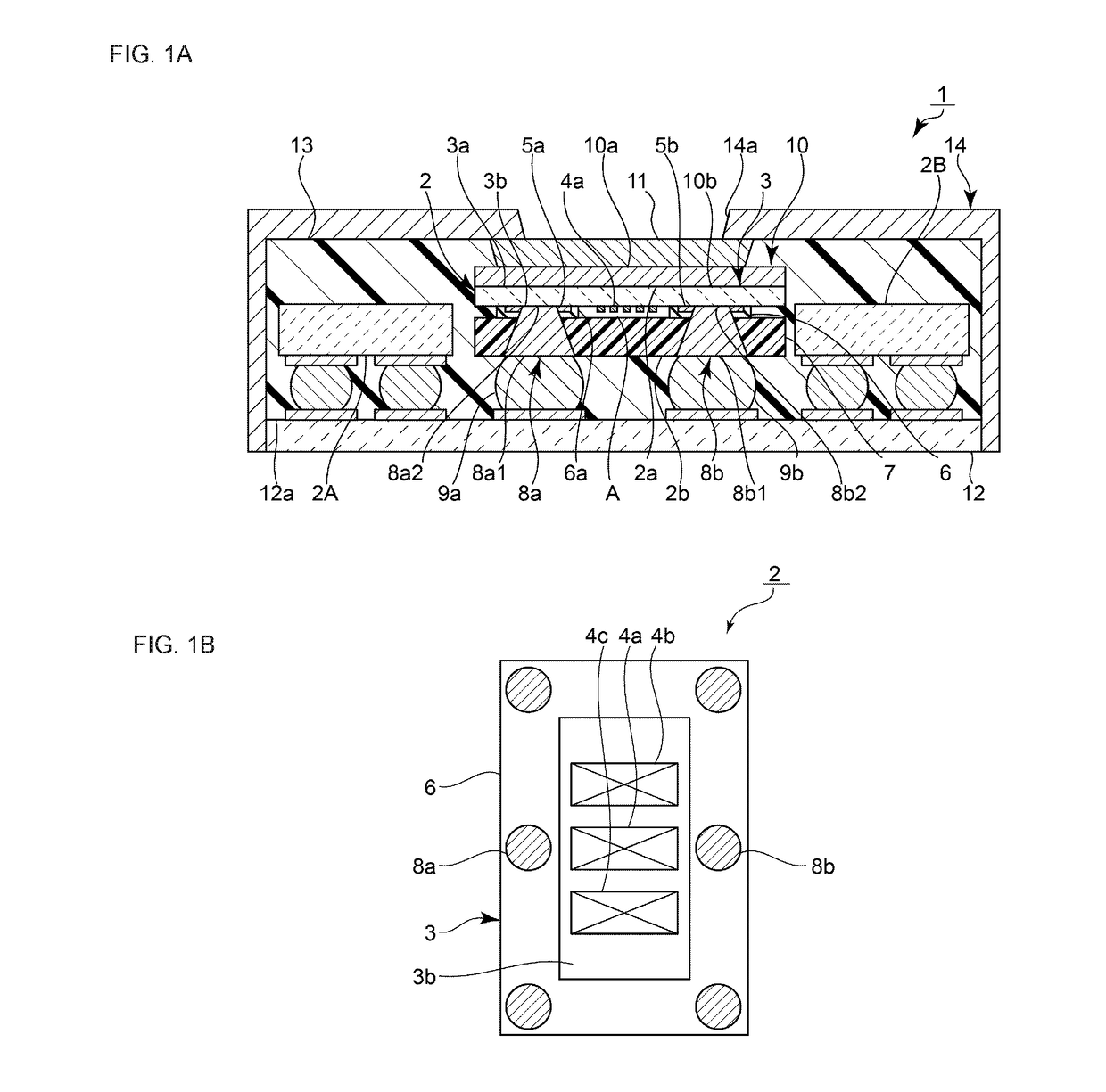
[0058]FIG. 1A is a sectional front view of an electronic component according to a first preferred embodiment of the present invention.

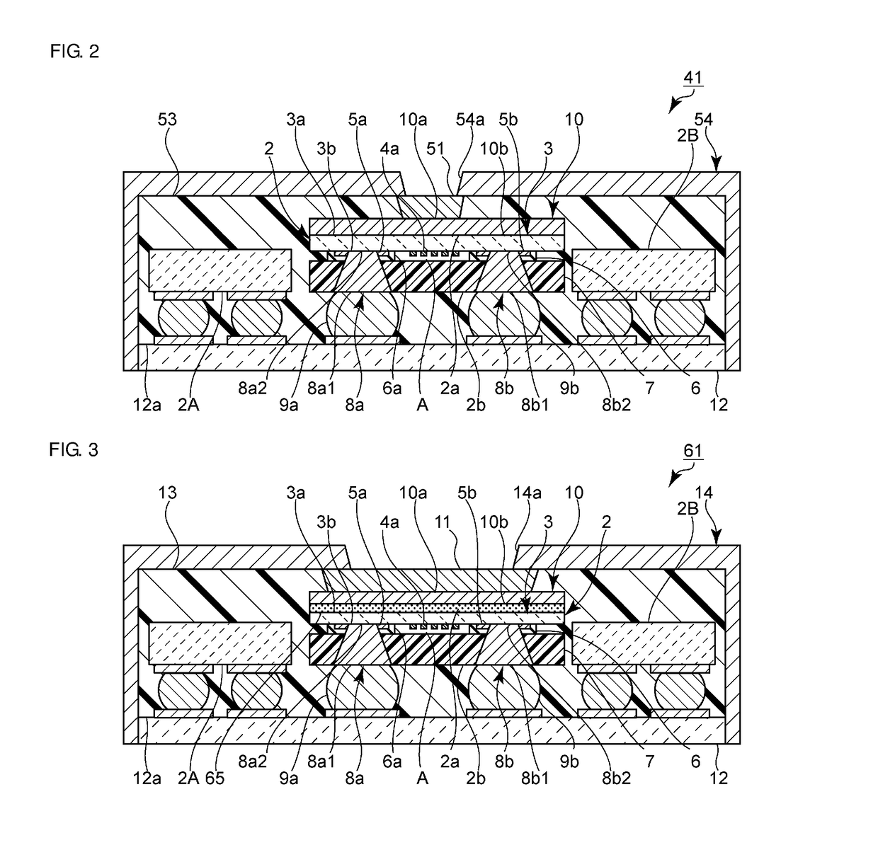
[0059]An electronic component 1 includes an electronic component element 2 mounted on a mounting substrate 12. More specifically, the electronic component element 2 includes first and second main surfaces 2a and 2b. The mounting substrate 12 includes a third main surface 12a opposing the second main surface 2a of the electronic component element 2. The electronic component element 2 is mounted at the second main surface 2b on the third main surface 12a of the moun...


PUM


Abstract

An electronic component includes an electronic component element including first and second main surfaces, a heat-dissipation accelerating member on the first main surface, a sealing resin layer sealing the electronic component element, and a shielding member provided on the sealing resin layer and electrically connected to the heat-dissipation accelerating member. The heat-dissipation accelerating member includes fourth and fifth main surfaces. The electronic component includes a connecting member disposed on the fifth main surface of the heat-dissipation accelerating member and electrically connecting at least one portion of the heat-dissipation accelerating member and the shielding member. The connecting member has a higher thermal conductivity than the sealing resin layer. The contact area between the heat-dissipation accelerating member and the connecting member is smaller than the area of the fifth main surface.

Description

CROSS REFERENCE TO RELATED APPLICATIONS[0001]This application claims the benefit of priority to Japanese Patent Application No. 2014-245792 filed on Dec. 4, 2014 and is a Continuation Application of PCT Application No. PCT / JP2015 / 083434 filed on Nov. 27, 2015. The entire contents of each application are hereby incorporated herein by reference.BACKGROUND OF THE INVENTION[0002]1. Field of the Invention[0003]The present invention relates to an electronic component including a shielding member and to a manufacturing method for the electronic component.[0004]2. Description of the Related Art[0005]Hitherto, an electronic component including a shielding member that provides an electromagnetic shielding function is widely used for an electronic device, such as a cellular phone.[0006]For example, in the electronic component disclosed in International Publication No. 2009 / 122835, an electronic component element is mounted on a circuit substrate. A conductive post connected to a ground potenti...

Claims


Application Information

Patent Timeline
IPC IPC(8): H05K1/18H03H9/02H05K3/30H01L41/047H05K1/02H05K3/28
CPCH05K1/18H05K1/0203H05K3/284H05K1/0216H05K3/30H05K2201/0707H03H9/02834H05K2201/10015H05K2201/1003H05K2201/10378H05K2201/10734H01L41/047H01L23/00H01L23/28H01L23/34H03H3/08H04B1/38H01L2924/0002H03H9/0542H03H9/059H03H9/1071H01L2924/00H10N30/87
Inventor KAWASAKI, KOICHIROKIKUCHI, TAKUKITAHARA, TAKASHINOTO, HIROKI
Owner MURATA MFG CO LTD
Learn More