Metal joint and manufacturing method therefor

a technology of metal joints and manufacturing methods, applied in the field of metal joints, can solve the problems of insufficient adhesion between materials, insufficient joint strength, and no contribution to improving joint strength, and achieve the effect of improving joint strength

Inactive Publication Date: 2017-09-07
HONDA MOTOR CO LTD
View PDF1 Cites 3 Cited by
  • Summary
  • Abstract
  • Description
  • Claims
  • Application Information

AI Technical Summary

Benefits of technology

[0015]The present inventor, et al., repeatedly carefully research surface modification used to promote adhesion between metallic joint surfaces of metal components to be bonded, and finally conceive of making the metallic joint surface molten and solidified to coarsen crystals and from brittle surface modification layers. In addition, it is found that if the surface modification layers are thin enough, the surface modification layers generate micro cracks due to deformation caused by riveting, and each segmented piece is peeled off starting from the cracks. Therefore, the following conclusion is derived: extremely smooth and unoxidized metal (fresh surfaces) is exposed; because the fresh surfaces are adhered to each other, joint strength is improved.

Problems solved by technology

For such local grooves, when metal components are deformed during riveting, a reach to a large depth of the groove indicates a difficult attempt to cause a sufficient plastic flow, and adhesion between materials becomes insufficient, and therefore joint strength is insufficient.
In addition, the subject of the technology disclosed in patent document 3 lies in preventing a shape or size of a metal joint from being deviated, and makes no contribution to improving joint strength.
Generally, in a process of riveted joint between metal plates, in most cases, an area or a joint depth of a joint portion cannot be sufficiently ensured.
Due to layout limitation, it is difficult to implement higher joint strength.

Method used


Image

  • Metal joint and manufacturing method therefor
  • Metal joint and manufacturing method therefor
  • Metal joint and manufacturing method therefor

Examples


embodiments

1. Embodiment 1 (Surface Modification Processing)

[0040]The present invention is described below in more detail with reference to an embodiment.

[0041]FIG. 3 is a photo of a surface of an aluminum (an aluminum alloy manufactured by KOBE STEEL LTD: 6K21) rolled material with a thickness of 1 mm. FIG. 3(A) is a photo photographed at a magnification of 100. FIG. 3(B) is a photo photographed at a magnification of 500. As shown in the drawings, micro traces of a rolling roller remain on the surface of the rolled material.

[0042]Second, a pulse laser apparatus (manufactured by Clean Laser System Company; power: 120 W; focal distance: 150 mm; pulse frequency: 10 kHz; scan frequency: 50 Hz) is used to perform surface modification on the rolled material. Pulse laser scanning is performed seamlessly on a whole surface of a local part of the rolled material.

[0043]FIG. 4 is a photo of a surface of a metal plate after surface modification is performed under the condition. FIG. 4(A) is a photo photo...

embodiment 2 (

2. Embodiment 2 (V-Shaped Bending Test)

[0044]According to Japanese Industrial Standards (JIS) Z2248, a V-shaped bending test is performed on the rolled material and the metal plate after surface modification. The V-shaped bending test is the following test, that is, making a male die and a female die that have a press surface bent into a V shape at a specified angle sandwich a sample to bend the sample. In the V-shaped bending test of the metal plate, a part after surface modification is located at an angular side of the V shape.

[0045]FIG. 5(A) is a photo of a surface of a rolled material before a V-shaped bending test. FIG. 5(B) is a photo of a surface of a bending portion of the rolled material after the V-shaped bending test. As shown in FIG. 5(B), large cracks of a metal oxide film are seen on the surface of the bending portion of the rolled material.

[0046]On the other aspect, FIG. 6(A) is a photo of a surface of a metal plate after surface modification before a V-shaped bending...

embodiment 3 (

3. Embodiment 3 (Riveted Joint)

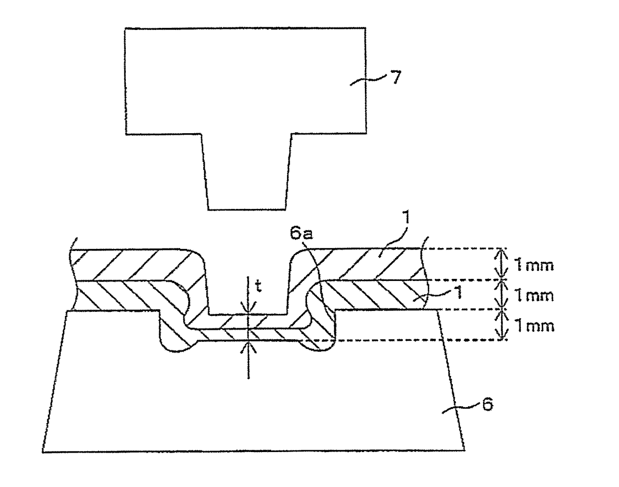
[0049]Metal oxide films of single surfaces of the rolled material used in Embodiment 1 are removed by using a wire brush, and two rolled materials are made overlapped to form laminated metal plate in a manner of making the surfaces face each other. In addition, two metal plates are made overlapped to form laminated metal plates in a manner of surface facing of surface modification performed in Embodiment 1. In this case, the rolled materials and the metal plates are set to be reed-shaped, and the rolled materials and the metal plates are staggered from each other to form laminated metal plates. A riveting apparatus (manufactured by TOX company) shown in FIG. 7 is used to shape the laminated metal plate into a shape shown in FIG. 7, and riveted joint is performed. The riveting apparatus is an apparatus having the following structure, that is, a die 6 with a recess 6a, and a punch 7, and the punch 7 is made to approach or far away from the die 6. A lower...


PUM

PropertyMeasurementUnit
thicknessaaaaaaaaaa
thicknessaaaaaaaaaa
thicknessaaaaaaaaaa

Abstract

The present invention provides a method for manufacturing a metal joint that promotes adhesion between metallic joint surfaces to improve joint strength. Pulse lasers are illuminated to at least surface portions, where riveting is to be implemented, of surfaces of metal plates (1), so that the surface portions are molten and solidified to form surface modification thin films (4); and multiple metal plates (1) are stacked to form a laminated metal plate (5) by facing the surface modification thin films (4) to each other, and pressurized shaping is performed on the laminated metal plate (5) by using a punch (7) and a die (6) to implement riveting.

Description

CROSS-REFERENCE TO RELATED APPLICATION[0001]This application claims the priority benefit of Japan application serial no. 2016-040962, filed on Mar. 03, 2016. The entirety of the above-mentioned patent application is hereby incorporated by reference herein and made a part of this specification.BACKGROUND OF THE INVENTION[0002]1. Field of the Invention[0003]The present invention relates to a metal joint and a manufacturing method therefor, and in particular, to a technology that improves joint strength. The metal joint is formed by implementing riveting on multiple metal components to make the metal components bonded with each other.[0004]2. Description of Related Art[0005]As regards technologies that perform joint on multiple metal components, for example, the following technology is known: as disclosed by the background of patent document 1, metal oxide films that exist on joint surfaces of metal components are removed by using a wire brush (wire brush), and the like to make unoxidi...

Claims


Application Information

Patent Timeline
Patent Type & Authority Applications(United States)
IPC IPC(8): F16B11/00B32B7/04B32B15/20B32B3/28B32B37/00B32B38/00B32B7/08B32B15/01
CPCF16B11/004B32B7/08B32B7/045B32B15/017B32B2311/24B32B37/0084B32B38/0008B32B15/20B32B2310/08B32B3/28B21D39/02F16B5/045B32B7/05
Inventor OOKA, HISAYASU
Owner HONDA MOTOR CO LTD
Why Eureka
Try Eureka