Machine tool and control apparatus of the machine tool

a technology of machine tools and control apparatuses, applied in the field of machine tools, can solve problems such as degradation of cutting efficiency, and achieve the effects of reducing the degradation of machining efficiency, and increasing machining efficiency

Active Publication Date: 2017-08-31
CITIZEN WATCH CO LTD
View PDF8 Cites 2 Cited by
  • Summary
  • Abstract
  • Description
  • Claims
  • Application Information

AI Technical Summary

Benefits of technology

The machine tool described in this patent can rotate the cutting tool at different speeds to improve cutting efficiency. During a repetitive movement at the second speed, the machine tool can achieve a smaller rotation angle, which reduces the impact of vibration. Additionally, the machine tool can limit the time period of air cuts, which further increases machining efficiency.

Problems solved by technology

Thus, the air cut is performed for more than one rotation of the spindle, causing degradation of cutting efficiency.

Method used


Image

  • Machine tool and control apparatus of the machine tool
  • Machine tool and control apparatus of the machine tool
  • Machine tool and control apparatus of the machine tool

Examples


Embodiment Construction

[0027]A machine tool and a control apparatus of the machine tool according to an aspect of the present invention may be embodied in an any manner as long as the repetitive movement unit is configured so that the cutting tool performs one repetitive movement with respect to multiple relative rotations between the workpiece and the cutting tool and so that a rotation angle of the relative rotation during the relative movement at the second speed is smaller than a rotation angle of the relative rotation during the relative movement at the first speed in one repetitive movement, for making it possible to cut the workpiece efficiently while the repetitive movement due to the relative movement at the mutually different first and second speeds is performed and to limit degradation of machining efficiency particularly when the repetitive movement constitutes a vibration.

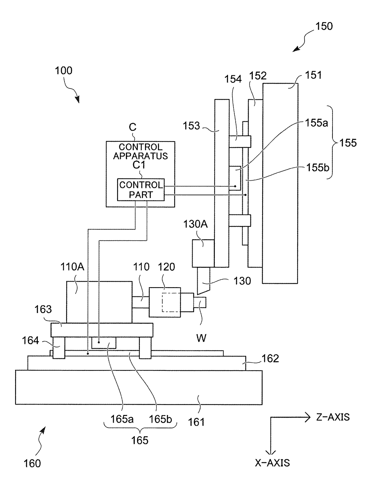
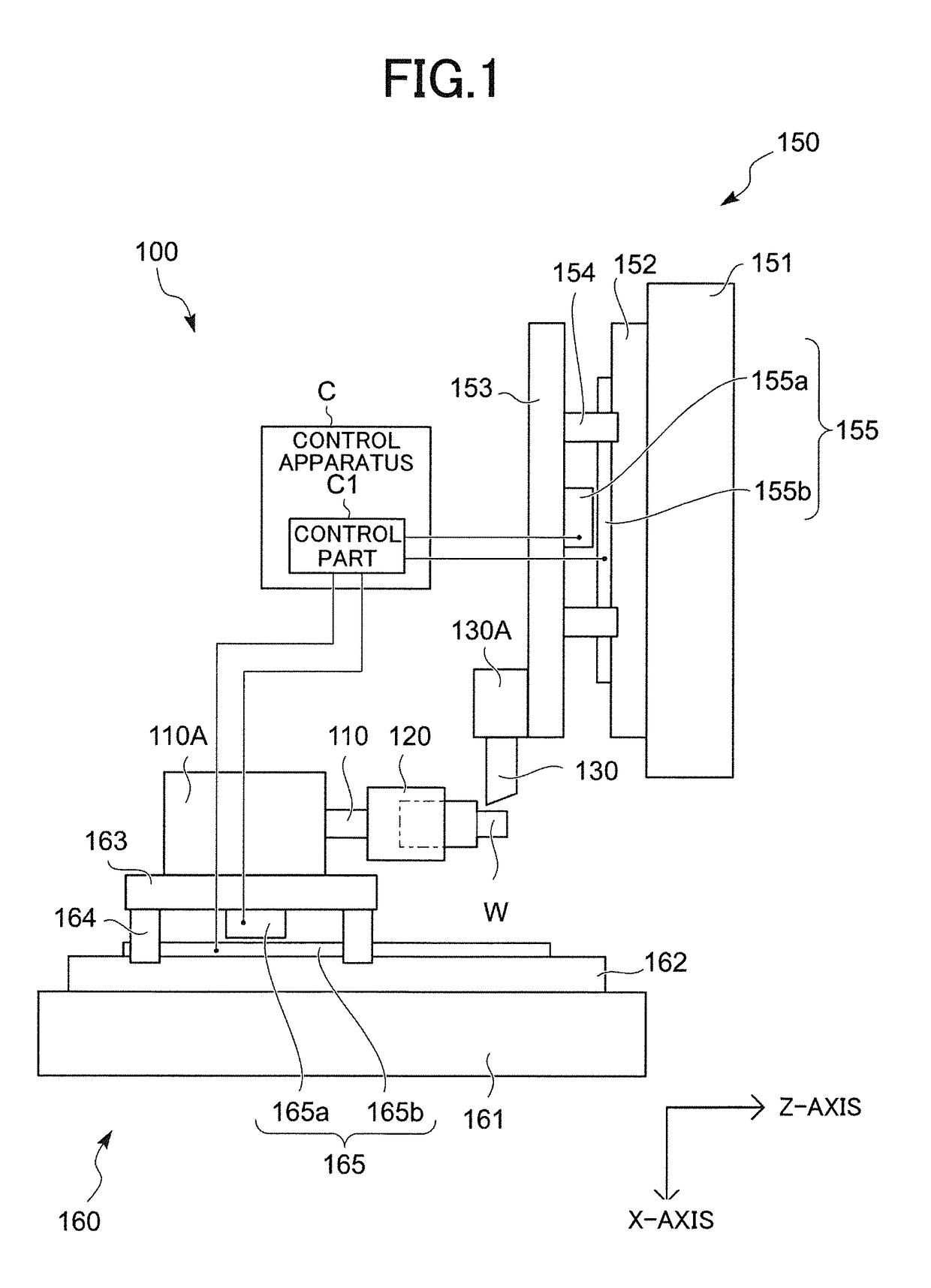
[0028]FIG. 1 is a diagram illustrating a machine tool 100 having a control apparatus C that is an embodiment of the presen...


PUM

PropertyMeasurementUnit
speedaaaaaaaaaa
rotation angleaaaaaaaaaa
lengthaaaaaaaaaa

Abstract

In a machine tool and a control apparatus thereof, a repetitive movement unit is configured so that the cutting tool performs one repetitive movement with respect to multiple relative rotations between the workpiece and the cutting tool and so that a rotation angle of the relative rotation between the workpiece and the cutting tool during relative movement at a second speed is smaller than a rotation angle of the relative rotation during relative movement at a first speed in one repetitive movement. This configuration limits degradation of machining efficiency when the cutting tool machines the workpiece by performing one repetitive movement with respect to multiple relative rotations between the workpiece and the cutting tool.

Description

FIELD OF THE INVENTION[0001]The present invention relates to a machine tool that machines a workpiece while sequentially separating a chip generated during cutting work, and also relates to a control apparatus of the machine tool.BACKGROUND OF THE INVENTION[0002]Conventionally, a machine tool is known that includes a workpiece holding unit to hold a workpiece, a tool rest to hold a cutting tool for cutting the workpiece, a feeding unit to feed the cutting tool toward the workpiece in a predetermined feeding direction via relative movement between the workpiece holding unit and the tool rest, a repetitive movement unit to repetitively move the workpiece holding unit and the tool rest in a mutually relative manner by repeating the relative movement in the feeding direction at a first speed and a second speed that are mutually different, and a rotating unit to relatively rotate the workpiece and the cutting tool, the machine tool being capable of machining the workpiece via the relativ...

Claims


Application Information

Patent Timeline
Patent Type & Authority Applications(United States)
IPC IPC(8): B23Q15/013G05B19/416B23B25/02
CPCB23Q15/013B23B25/02G05B2219/49355G05B2219/36204G05B19/416B23B1/00G05B2219/49055G05B2219/45136
Inventor SANNOMIYA, KAZUHIKOMATSUMOTO, HITOSHIIMASAKI, NOBUYOSHI
Owner CITIZEN WATCH CO LTD
Why Eureka
Try Eureka