
Gamma setting system of display device and gamma setting method thereof

a display device and gamma setting technology, applied in the field of gamma setting system of a display device, can solve the problems of source current driving emissive display device, distortion of white balance, and the effect of reducing the error or the contribution of variables, improving the yield and widening the setting rang

Active Publication Date: 2017-08-03
LIM JUMI
View PDF0 Cites 14 Cited by
  • Summary
  • Abstract
  • Description
  • Claims
  • Application Information

AI Technical Summary

Benefits of technology

The present invention relates to a gamma setting system and method for a display device. The technical effects of the invention include improved yield, wider setting range, reduced setting time, and improved productivity. The invention uses a current efficiency measurement to set gamma resistance and gamma voltage, resulting in a higher accuracy and wider setting range. A transfer function is calculated to obtain the target luminance, and a minimum and maximum allowable deviation in white luminance and chromaticity is set. The invention also adjusts samples with non-uniform efficiency, improves yield, prevents skin effect, reduces setting time, and improves productivity. The invention also reduces the time to find the optimum value of the ladder resistor and reduces the deviation due to voltage error. A lookup table and histogram are used to set the gamma setting time for a new sample, improving productivity.

Problems solved by technology

However, the emissive display device of a source current driving type has disadvantages such as a deviation in a diode and a transistor caused by a fabrication process of a back plane, a distortion of white balance caused by a deviation in a material and a fabrication process of an emitting element and a crosstalk according to a voltage drop (IR drop) caused by a deviation in an operational load of a sub-pixel when driven by a source current.
The results according to the conventional compensation methods may be changed by an error or a contribution of variables due to excessively complicate equations or excessively many related variables.
In addition, the results according to the conventional compensation methods may be changed by an inconsistent fabrication process.
As a result, the conventional compensation methods have been used within an allowable error range of the variables due to deviation in a fabrication process with a relatively low accuracy.
In addition, when a chromaticity of a white is compensated using an XYZ coordinate system of a tri-stimulus value, a chromaticity calculation according to an exact red-green-and-blue (RGB) luminance may not be performed.
Accordingly, a fabrication time increases and a productivity decreases due to a long time for compensation.
As a result, a long operation time through trial and error is required.
Accordingly, the conventional compensation methods using a lookup table has disadvantages in accuracy and operation time.
In addition, since a repetitive process for convergence is required, a long time is taken for compensation.
Further, since consistency of variation in efficiency is degraded due to a fabrication process for each sample, samples where a lookup table with respect to a reference sample is applied is limited.
The above disadvantages function as a hindrance factor in improvement of yield of wider samples.

Method used


Image

  • Gamma setting system of display device and gamma setting method thereof
  • Gamma setting system of display device and gamma setting method thereof
  • Gamma setting system of display device and gamma setting method thereof

Examples


first embodiment

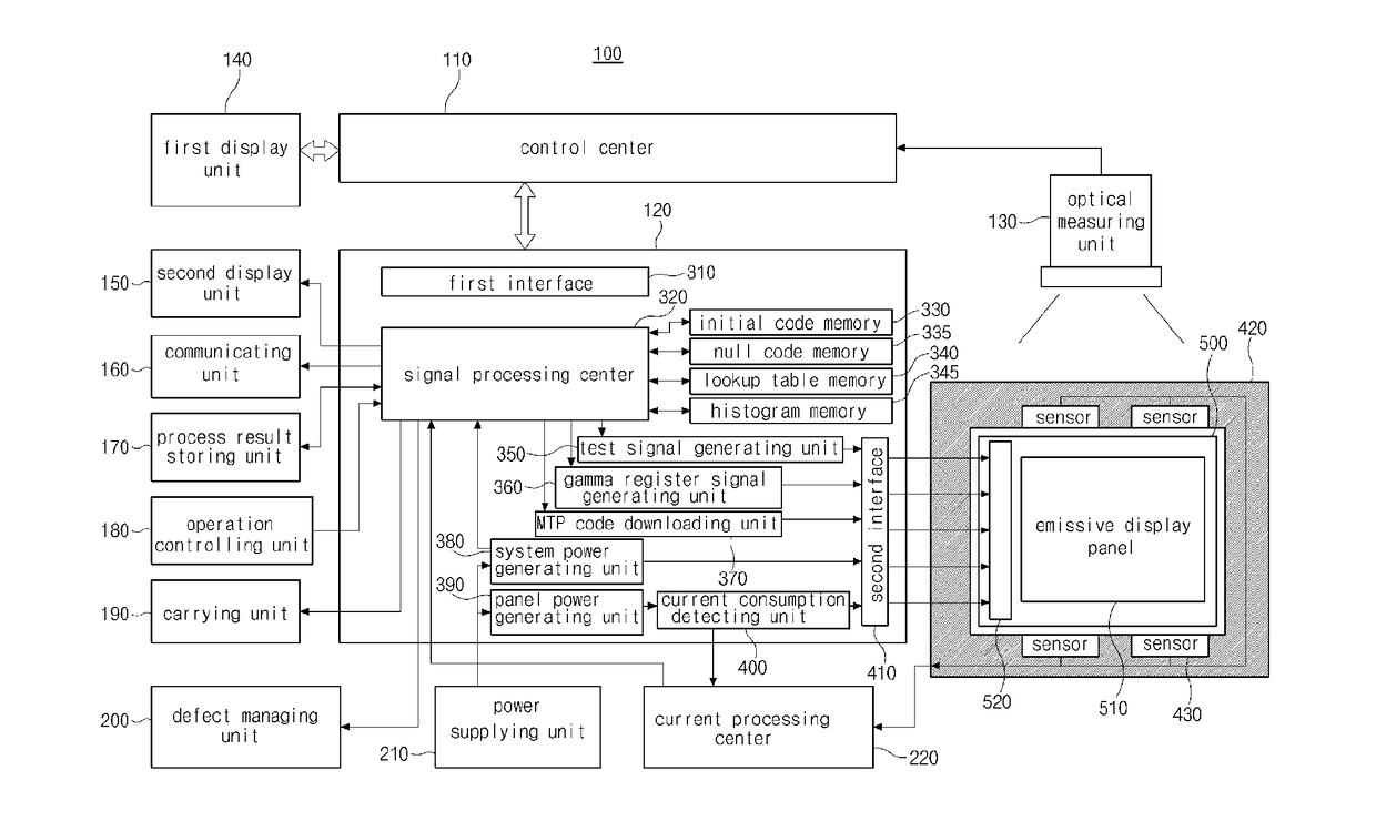
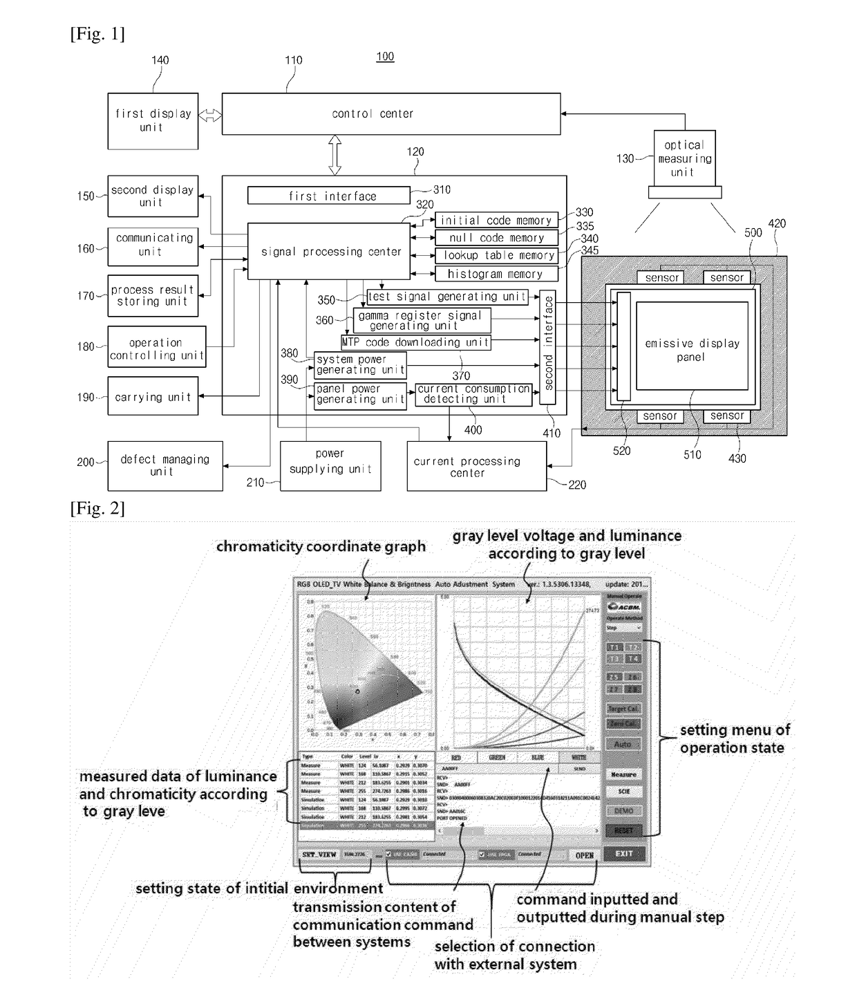
[0040]In FIG. 1, a gamma setting system 100 according to the present invention includes primary units such as a control center 110, a system driving unit 120 and an optical measuring unit 130 and secondary units such as first and second displaying units 140 and 150, a communicating unit 160, a process result storing unit 170, an operation controlling unit 180, a carrying unit 190, a defect managing unit 200, a power supplying unit 210, a current processing center 220 and a sample supporting unit 420.

[0041]The control center 110 is an application processor (AP) system for supplying an operation command signal of a null setting step and an automatic setting step to the system driving unit 120. For example, the control center 110 may be a computer while a display device is fabricated, and the control center 110 may be a micro computer unit (MCU) after a display device is fabricated.

[0042]The control center 110 performs the null setting step and the automatic setting step for setting a ...

second embodiment

[0158]In FIG. 14, a gamma setting method of a display device according to the present invention includes a null setting step st110 performed under a new environment or under an identical environment regularly / irregularly and an automatic setting step st150 performed under an identical environment.

[0159]The gamma setting system according to a second embodiment of the present invention selects and performs one of the null setting step st110 and the automatic setting step st150, or performs both of the null setting step st110 and the automatic setting step st150. When both of the null setting step st110 and the automatic setting step st150 are performed, the automatic setting step st150 may be performed after the null setting step st110.

[0160]The null setting step st110 and the automatic setting step st150 may be performed using an RGB luminance, a PW luminance and a TW luminance by a direct measurement of the optical measuring unit 130 with respect to an identical input gamma power. T...

third embodiment

[0192]In FIG. 15, a gamma setting system 600 according to the present invention includes a control center 610, a signal processing unit 620, a current processing center 630, a sample supporting unit 640 and an optical measuring unit 650.

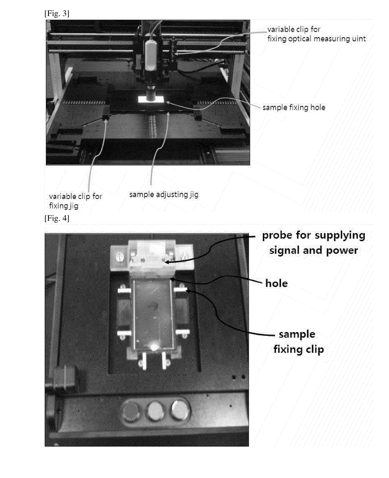
[0193]The sample supporting unit 640 fixes a position of the emissive display panel (including the driving IC) for protection. In addition, the sample supporting unit 640 transmits the test signal of the signal processing center 620 to the emissive display panel, and transmits the measured signal such as the photo current of the emissive display panel to the current processing center 630. For example, a jig or a pallet may be used as the sample supporting unit 640.

[0194]The sample supporting unit 640 may include a measuring device such as a sensor 642 in periphery of the emissive display panel, and the sensor 642 may generate a photo current corresponding to a luminance of a light emitted from the emissive display panel.

[0195]The display device 660 i...


PUM


Abstract

The present invention provides a gamma setting system for a display device including: an optical measuring unit measuring an optical property of a display device including an emissive display panel having red, green and blue sub-pixels; a control center performing a null setting step and an automatic setting step using the optical property of the display device; a system driving unit transmitting a result data between the display device and the control center; a first display unit displaying a TW target luminance, a TW target chromaticity and an RGB inherent chromaticity registered for the null setting step and the automatic setting step, a graph of a gray level voltage and a luminance of an RGB and a TW with respect to a gray level, a high level cell driving voltage (PVDD) and a low level cell driving voltage (PVEE) applied to an emitting element, a high level gamma source voltage (VDDH) and a low level gamma source voltage (VDDL) applied to a driving IC, a gamma slope, a contrast ratio, a driving type of the system, a gamma setting, an instruction on an execution command, and a progress state of the display device.

Description

TECHNICAL FIELD[0001]The present invention relates to a gamma setting system of a display device, more particularly, to a gamma setting system of an emissive display device of a source current driving type where a gamma resistance and a gamma voltage are directly set using an optical property of the display device and a gamma setting method of the gamma setting system.BACKGROUND ART[0002]An emissive display device of a source current driving type displays an image using an organic diode, a quantum dot diode, an organic transistor or a quantum dot transistor and has advantages such as a light weight, a thin profile and a low power consumption.[0003]However, the emissive display device of a source current driving type has disadvantages such as a deviation in a diode and a transistor caused by a fabrication process of a back plane, a distortion of white balance caused by a deviation in a material and a fabrication process of an emitting element and a crosstalk according to a voltage dr...

Claims


Application Information

Patent Timeline
Patent Type & Authority Applications(United States)
IPC IPC(8): H04N5/202G09G3/00H04N5/57
CPCH04N5/202H04N5/57G09G2320/0673G09G5/10G09G3/006G09G3/3208G09G5/02G09G2310/0221G09G2320/0693H04N17/02H04N17/04
Inventor JUNG, TAE-BOBAE, BYUNG-SEONGCHOI, DON-SAM
Owner LIM JUMI
Learn More