Iterative reconstruction method for spectral, phase-contrast imaging

a reconstruction method and phase-contrast technology, applied in the field of signal processing system, can solve the problems of high image noise level of phase-contrast computed tomography and ct compton cross-section absorption imagery, and may be expensive to procure energy-resolving detectors, and achieve the effect of less nois

Active Publication Date: 2017-07-20
KONINKLJIJKE PHILIPS NV
View PDF2 Cites 8 Cited by
  • Summary
  • Abstract
  • Description
  • Claims
  • Application Information

AI Technical Summary

Benefits of technology

[0019]In sum, the proposed system advantageously circumvents the generation of an entire dataset, namely the line integral of electron density. This has a further advantage in that the eve...

Problems solved by technology

It has been observed that phase-contrast computed tomography (CT) imagery and CT Compton cross-section absorption imagery (obtained from a spectral material decomposition) are inflicted by relatively high image noise levels in the high frequency range for phas...

Method used


Image

  • Iterative reconstruction method for spectral, phase-contrast imaging
  • Iterative reconstruction method for spectral, phase-contrast imaging
  • Iterative reconstruction method for spectral, phase-contrast imaging

Examples


Embodiment Construction

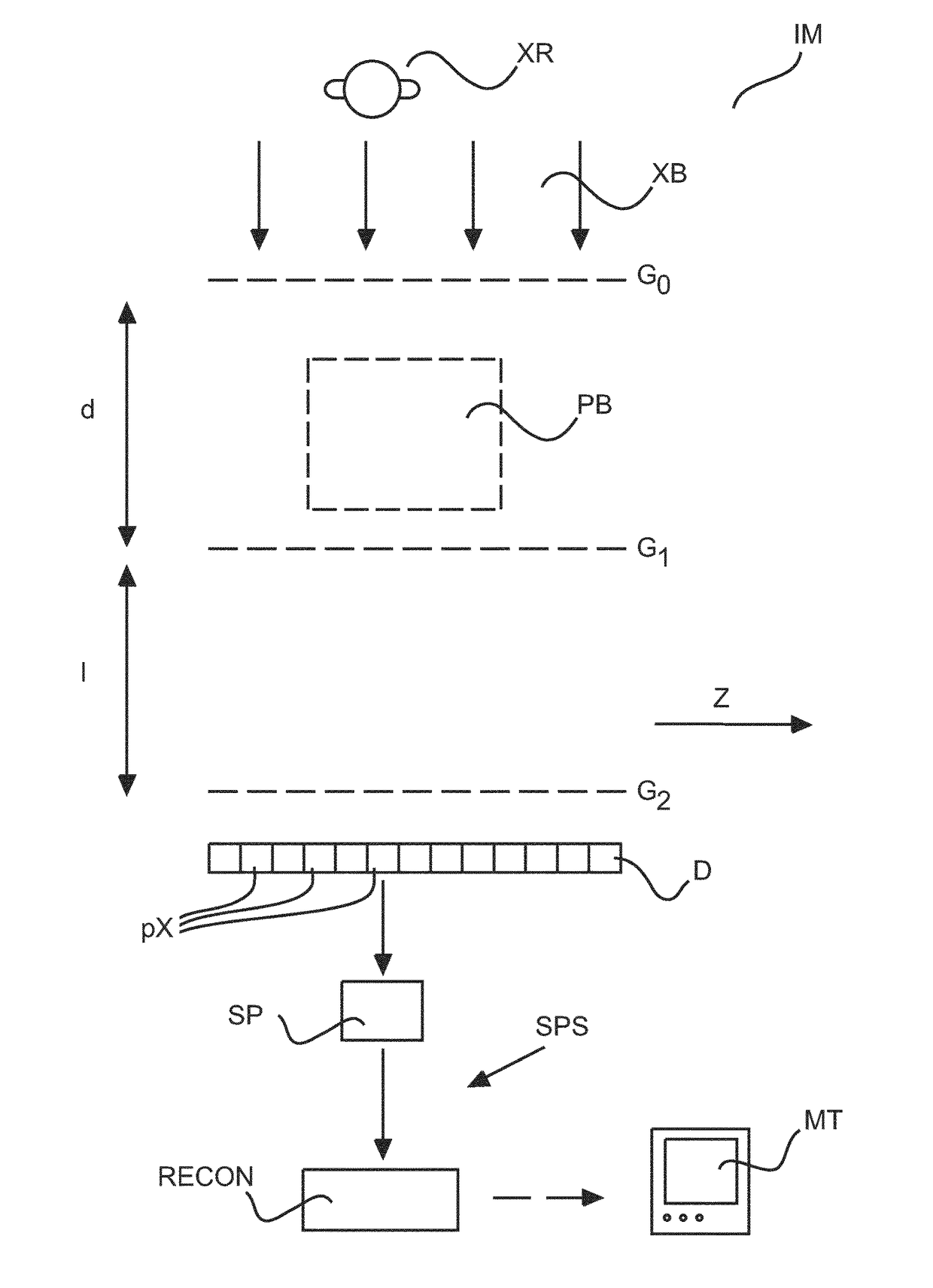
[0024]FIG. 1 shows basic components of an imaging system IM with phase contrast imaging capabilities, in particular differential phase contrast imaging (DPCI).

[0025]There is an X-ray source XR for generating X-ray radiation waves XB that, after passage through a specimen PB in an examination region, are detectable by detector pixels px of a detector D. An object support (not shown) such as a couch supports the specimen PB (such as a patient or an inanimate object, e.g. an item of baggage, etc) in the examination region.

[0026]The imaging system IM is either a CT scanner for 3D imaging or may also be a simpler planar projection imager apparatus such as of the C-arm type. At least the x-ray source is mounted on a rotatable gantry to project the x-ray waves through the patient at any one or a plurality of desired projection directions.

[0027]The phase contrast imaging capability is achieved by an interferometer arranged between the X-ray source XR and the radiation sensitive detector D.

[...


PUM


Abstract

A system and related method for X-ray phase contrast imaging. A signal model is fitted to interferometric measurment data. The fitting operation yields a Compton cross section and a photo-electric image. A pro-portionality between the Compton cross section and electron-density is used to achieve a reduction of the number of fitting variables. The Compton image may be taken, up to a constant, as a phase contrast images.

Description

FIELD OF THE INVENTION[0001]The invention relates to signal processing system, to a signal processing method, to a computer program element and to a computer readable medium.BACKGROUND OF THE INVENTION[0002]It has been observed that phase-contrast computed tomography (CT) imagery and CT Compton cross-section absorption imagery (obtained from a spectral material decomposition) are inflicted by relatively high image noise levels in the high frequency range for phase-contrast imaging and the low frequency range for spectral imaging, respectively. What is more, spectral material decomposition may require special detector hardware, in particular photon-counting and / or energy resolving detectors, which may be expensive to procure.SUMMARY OF THE INVENTION[0003]There may therefore be a need for alternative image signal processing methods and related systems to address at least some of the above mentioned disadvantages.[0004]The object of the present invention is solved by the subject matter...

Claims


Application Information

Patent Timeline
IPC IPC(8): G06T11/00A61B6/03G01N23/20A61B6/00
CPCG06T11/008A61B6/484G01N23/20075A61B6/5205A61B6/032G06T11/006
Inventor ROESSL, EWALDKOEHLER, THOMAS
Owner KONINKLJIJKE PHILIPS NV
Why Eureka
Try Eureka