Mulit-layer film
a multi-layer film and film technology, applied in the field of multi-layer films, can solve the problems of increasing the amount of dust and the possibility of generating dust, significant damage to the film, and damage to the clear material base sheet, and achieve the effect of facilitating the slitting process
- Summary
- Abstract
- Description
- Claims
- Application Information
AI Technical Summary
Benefits of technology
Problems solved by technology
Method used
Image
Examples
first embodiment
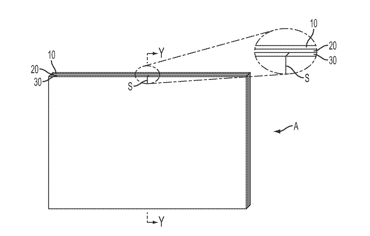
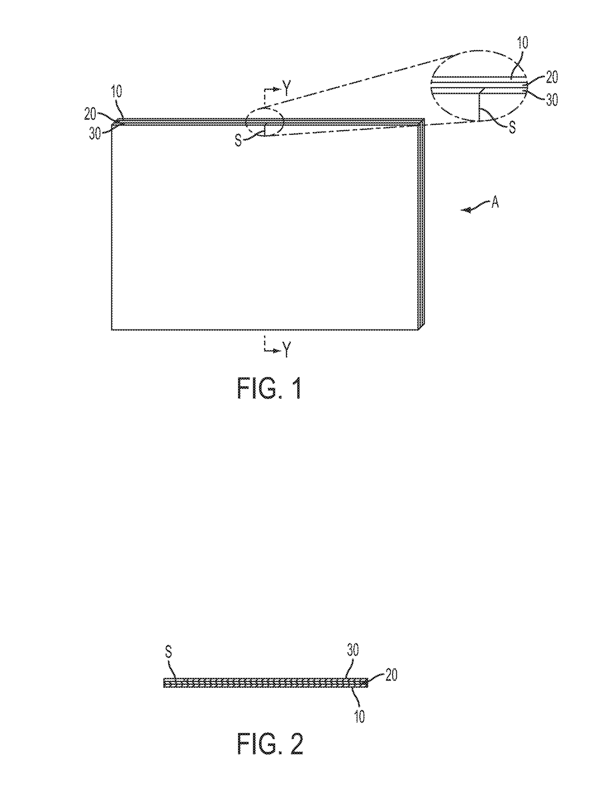
[0049]FIG. 1 is a perspective view of the multi-layer film A according to the first embodiment of this invention, andFIG. 2 is a cross section view of the multi-layer film A of the first embodiment taken along the line Y-Y;
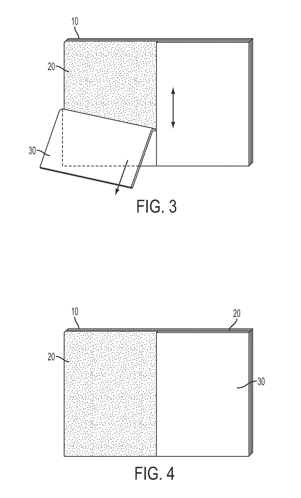
[0050]The multi-layer film A according to this embodiment is a rectangular film having a clear material base sheet 10, an adhesive layer 20, and a separator 30.
[0051]This multi-layer film is structured so that a front surface of the clear material base sheet 10 is exposed to the user and this front surface has scratch resistant properties so as to protect the film surface when used by the user, the adhesive layer 20 is created on a back surface of the clear material base sheet 10, and the separator 30 is temporarily placed and attached to the adhesive layer 20.
[0052]The clear material base sheet 10 for example can be an entirely clear material, it can be a reflection sheet, a polarizing sheet, a clear sheet with decoration, a semi-transparent sheet, a phase differ...
second embodiment
[0068]FIG. 7 is a perspective view of the multi-layer film A according to the second embodiment of this invention, and FIG. 8 is a cross section view of the multi-layer film A of the second embodiment taken along the line Y-Y.
[0069]The multi-layer film sheet A of the second embodiment has the slit S in an intermediate portion of the separator 30, as in the first embodiment, but the slit S is deeper than the slit S in the first embodiment so that it goes into the adhesive layer 20. Although the slit S is short and should stop at the adhesive layer 20, the quality of the film A after completion of the installation would not be affected even if the blade accidentally goes into the clear material base sheet 10. The installation process is the same as the first embodiment and the explanation of which will be omitted here.
third embodiment
[0070]FIG. 9 is a perspective view of the multi-layer film A according to the third embodiment of this invention, and FIG. 10 is a cross section view of the multi-layer film A of the third embodiment taken along the line Y-Y. The multi-layer film A of the third embodiment has an effective area P1 which is installed on the electronic device display and a disposable area P2 which can be disposed after installing the film on the display. The effective area P1 is a film placed on the display and the disposable area P2 is disposed after tearing and separating from the effective area P1. A detach line D is formed on the clear material base sheet 10 and the adhesive layer 20 between the effective area P1 and the adjacent disposable area P2. The disposable area P2 can be in any shape but in this embodiment the disposable area P2 has the same width along the detach line D.
[0071]The slit S in this embodiment is positioned at a central portion of the multi-layer film A within the disposable ar...
PUM
| Property | Measurement | Unit |
|---|---|---|
| thickness | aaaaa | aaaaa |
| thickness | aaaaa | aaaaa |
| thickness | aaaaa | aaaaa |
Abstract
Description
Claims
Application Information
 - R&D Engineer
- R&D Manager
- IP Professional
- Industry Leading Data Capabilities
- Powerful AI technology
- Patent DNA Extraction
Browse by: Latest US Patents, China's latest patents, Technical Efficacy Thesaurus, Application Domain, Technology Topic, Popular Technical Reports.
© 2024 PatSnap. All rights reserved.Legal|Privacy policy|Modern Slavery Act Transparency Statement|Sitemap|About US| Contact US: help@patsnap.com


