
Ice machine with a dual-circuit evaporator for hydrocarbon refrigerant

a technology of hydrocarbon refrigerant and ice machine, which is applied in the direction of compression machines with several condensers, applications, lighting and heating apparatus, etc. it can solve the problems of inability to determine the indirect release of refrigerant over the life of the equipment due to infinitely small leakage, and the ice is usually of poor quality, so as to save material costs and ensure the effect of ice production

Active Publication Date: 2017-06-22
TRUE MFG CO INC
View PDF15 Cites 26 Cited by
  • Summary
  • Abstract
  • Description
  • Claims
  • Application Information

AI Technical Summary

Benefits of technology

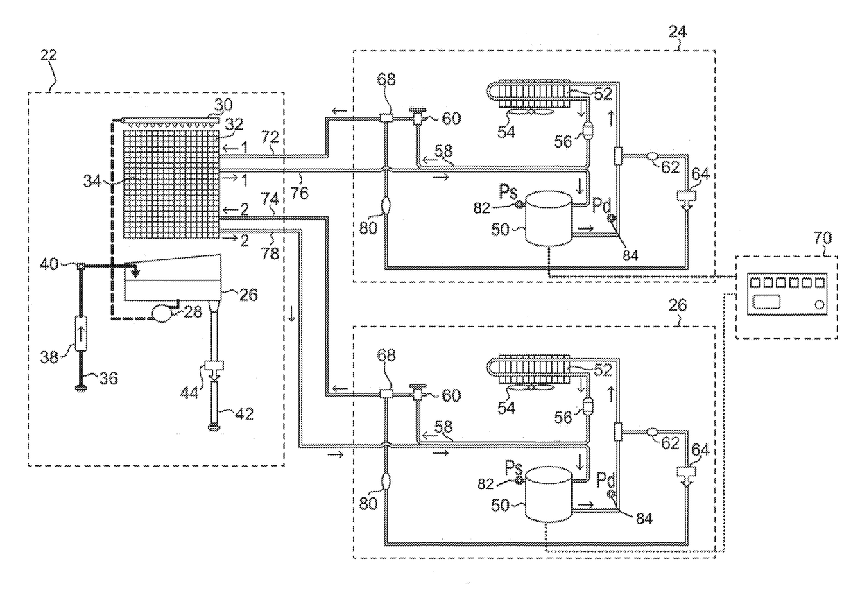
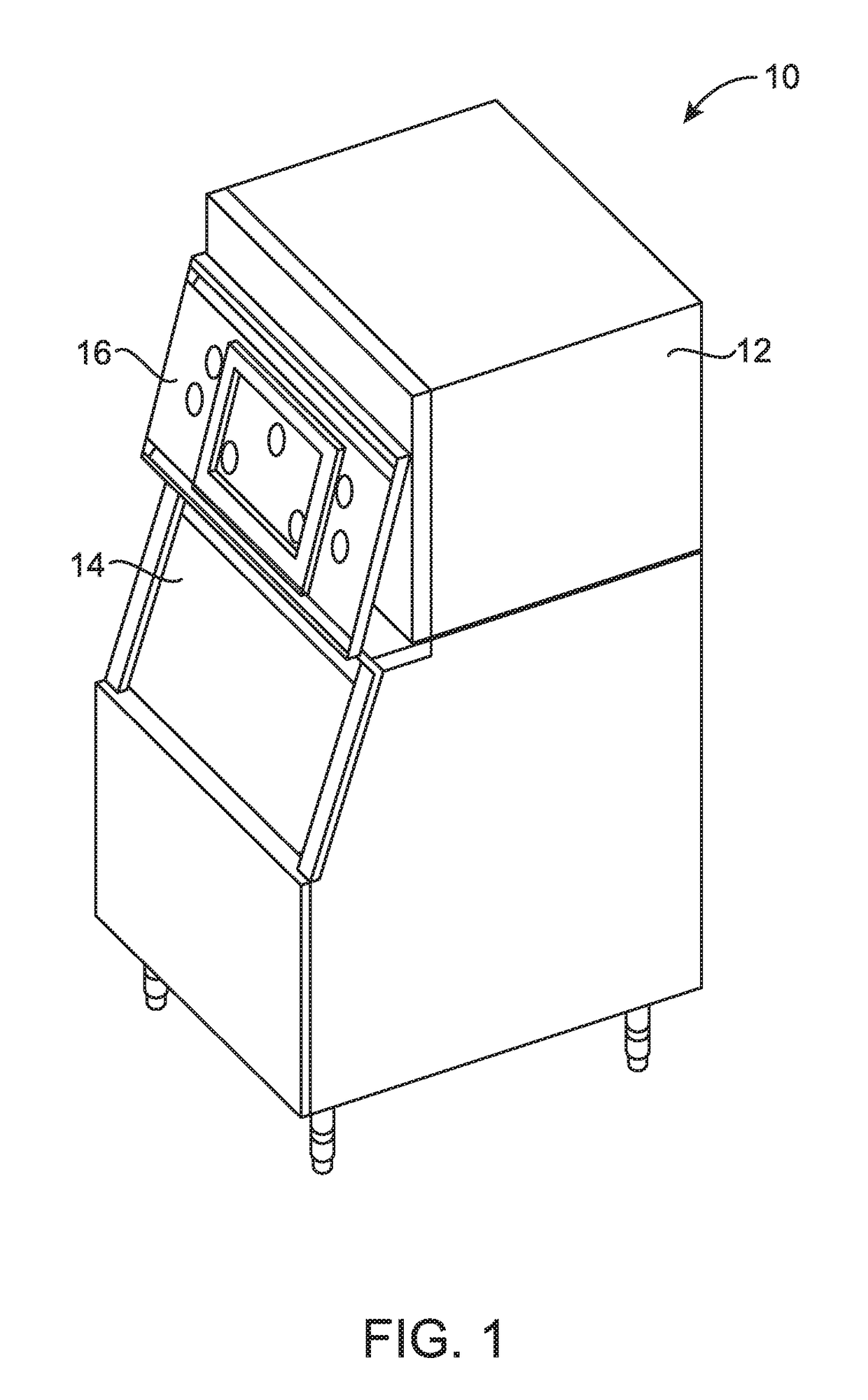
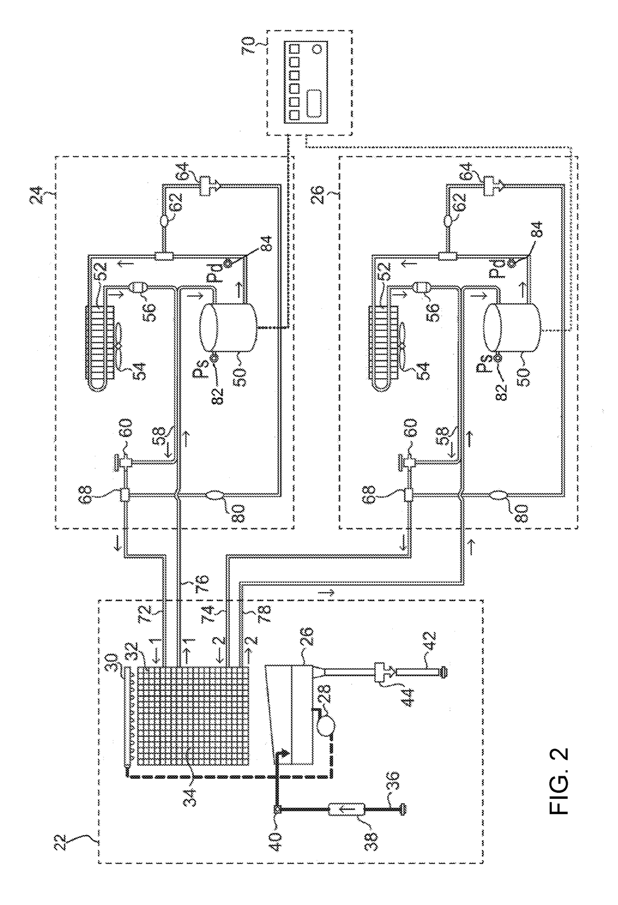
This patent is about a new way to make ice using a single evaporator and two hydrocarbon refrigeration systems. This method is safer and more cost-effective than traditional ice makers. The invention involves a unique design that allows for higher ice capacity while operating within the limits of hydrocarbon refrigerants. This innovation involves a single freeze plate, a single water circulation system, and a single microprocessor to monitor and control the ice production process. The technical effects of this patent include higher ice production with safer and more cost-effective equipment.

Problems solved by technology

The resulting ice is usually of poor quality due to the trapping of air and impurities during the freezing process.
Despite its optimum fit for the application, R-404a is receiving increasingly negative attention about its effect on the environment.
Its direct release to the atmosphere is prohibited, however, the indirect release of refrigerant over the life of the equipment due to infinitesimal leakage can be nearly impossible to ascertain.
An even greater impact exists with the indirect effect of the increased energy consumption required of equipment running on a reduced charge.
The aforementioned HFO blends have a comparatively high temperature glide which make them unsuitable for the application.
It can essentially be dropped into existing systems without major modification; however, R-290 poses its own set of design challenges due to its flammability.
However, microchannel condensers are traditionally more expensive than fin and tube condensers, and with a volume of only 250 ml, there still remains a limit on the maximum ice capacity that can be obtained with such a condenser.
Ice manufacturers have successfully made 500 pounds of ice per day with 150 grams of propane, but no solution exists for icemakers requiring greater capacity in a single system.
However, the cost of multiple systems would make the product unprofitable.
The evaporator, being made of a high thermal conductive material such as copper, is in some cases the most expensive component of an ice making machine.
There could also be some significant performance-related drawbacks.
A dual-evaporator system with cycling control would scale or corrode one evaporator more rapidly than the other resulting in more frequent failures of one side, effectively reducing the ice making capacity in half.
The increased warranty costs for a hydrocarbon dual evaporator system drastically effect the business case and consume any potential profits as compared with the single HFC system evaporator standard of the day.
Therefore, the current solutions presented for R-290 unfortunately offer little solution for larger ice making machines in a competitive market driven to reduce overall costs, especially with emerging manufacturers from around the world offering new competition.
However, this method is unproven in the market and there is little evidence that flat conduit would last the duration of the icemakers service life due to the high probability of plate-tube separation.
Surface imperfections in the flatness would cause pockets of air between the plate and tube, and ultimately lead to the build-up of ice between the two surfaces.
Over repeated thermal cycling, the ice would expand to propagate behind the freeze plate, which lead to a reduced ice capacity and ultimately complete failure.
Nonetheless, there will always be a charge limitation for use of flammable refrigerants for commercial equipment located and installed indoors.

Method used


Image

  • Ice machine with a dual-circuit evaporator for hydrocarbon refrigerant
  • Ice machine with a dual-circuit evaporator for hydrocarbon refrigerant
  • Ice machine with a dual-circuit evaporator for hydrocarbon refrigerant

Examples


Embodiment Construction

[0019]Before any embodiments of the invention are explained in detail, it will be understood that the invention is not limited in its application to the details of construction and the arrangement of components set forth in the following description or illustrated in the following drawings. The invention is capable of other embodiments and of being practiced or of being carried out in various ways. Also, it will be understood that the phraseology and terminology used herein are for the purpose of description and should not be regarded as limiting. The use of “including,”“comprising,” or “having” and variations thereof is meant to encompass the items listed thereafter and equivalents thereof as well as additional items. All numbers expressing measurements and so forth used in the specification and claims are to be understood as being modified in all instances by the term “about.” It should also be noted that any references herein to front and back, right and left, top and bottom and ...


PUM


Abstract

An ice making machine having a refrigeration system designed for hydrocarbon (HC) refrigerants, and particularly propane (R-290), that includes dual independent refrigeration systems and a unique evaporator assembly comprising of a single freeze plate attached to two cooling circuits. The serpentines are designed in an advantageous pattern that promotes efficiency by ensuring the even bridging of ice during freezing and minimizing unwanted melting during harvest by providing an even distribution of the heat load. The charge limitations imposed with flammable refrigerants would otherwise prevent large capacity ice maker from being properly charged with a single circuit. The ice making machine includes a single water circuit and control system to ensure the proper and efficient production of ice. Material cost is conserved as compared to a traditional dual system icemaker.

Description

CROSS-REFERENCE TO RELATED APPLICATIONS[0001]This application claims priority to, and incorporates by reference, U.S. provisional patent application Ser. No. 62 / 270,391, filed Dec. 21, 2015.FIELD OF THE INVENTION[0002]This invention relates generally to automatic ice making machines and, more specifically, to ice making machines using hydrocarbon refrigerants, such as propane, with a unique evaporator comprising of a single freeze plate attached to dual, independent refrigerant circuits that are designed in such a way as to ensure the even production of ice across the evaporator, thus allowing an increased ice production capacity within the allowable limit of system charge.BACKGROUND[0003]Ice making machines are employed in commercial and residential applications around the world. In domestic applications, ice makers are typically located in a freezer compartment. The resulting ice is usually of poor quality due to the trapping of air and impurities during the freezing process. In c...

Claims


Application Information

Patent Timeline
Patent Type & Authority Applications(United States)
IPC IPC(8): F25C1/04F25B6/02F25C1/22
CPCF25C1/225F25B6/02F25C1/04F25C2600/04F25C2700/04F25B2400/12F25B25/005F25B39/02F25B40/00F25B47/022F25B2339/023F25B2400/06F28F2210/10F25C1/12F28D1/0477F25C2400/10F25B2400/00F25C1/25F25B5/02
Inventor KNATT, KEVIN
Owner TRUE MFG CO INC
Learn More