
Porous Interbody Spacer

a spacer and interbody technology, applied in the field of spinal fusion implants, can solve the problems of limited success of such devices, bone cannot or will not grow, and cannot bridge the gap, and achieve the effect of correcting the pore siz

Inactive Publication Date: 2017-06-08
NEXUS SPINE L L C
View PDF7 Cites 86 Cited by
  • Summary
  • Abstract
  • Description
  • Claims
  • Application Information

AI Technical Summary

Benefits of technology

The invention provides orthopedic implants, particularly interbody spacers, that have a combination of correct pore size and stiffness, which allows osteocytes to properly bridge the pores of the implant and stimulate bone growth. The implants have a stiffness between 400 MPa and 1,200 MPa and may be manufactured using an additive manufacturing process. The implants may be made from titanium, tantalum, or alloys thereof. The invention also provides methods for manufacturing the implants. The technical effects of the invention include promoting bone growth and reducing the risk of complications during spine surgery.

Problems solved by technology

When proper conditions are not available, bone cannot or will not grow.
Additionally, when gaps to be filled are too large or too small, bone cannot bridge the gap and will not grow.
Finally, because bone growth is impeded by the presence of certain materials and / or chemicals, an absence of such materials and chemicals is required for proper bone growth.
These techniques have been used in implants for years with varying degrees of success, but the success of such devices has been limited by the devices' ongoing failure to provide physical and chemical characteristics most conducive to bone growth.
Even when a graft is present in a cavity or void, any bone that does form on or around the device is of lesser quality and quantity.
Generally, current implants have one or more characteristics that are not maximally conducive to facilitating bone growth into the implant.
For example, some implants may provide a pore size that is generally within a desirable range, but may have a stiffness that is too high to allow bone within the porous structure of the implant to be properly loaded.
As a result, the bone will not take advantage of the correct porosity and pore size of such implants, and will grow only minimally, if at all, in the porous structure of such implants.
As a result, while the bone cells can be properly loaded, they are unable to grow bone in the available pores.
Unfortnuately, PEEK is not chemically a bone-friendly material.
These devices are typically too stiff even in their porous regions.
As a result, while such devices may achieve bone on-growth at the surface of the device, such devices do not achieve ingrowth that extends throughout the devices.
Due to the lack of proper loading, bone does not grow within the Zimmer devices to a significant extent.
As a result, any bone that does enter the pores of the device cannot be properly loaded, and ingrowth does not occur.
The stiffness of the Stryker device may exceed the stiffness of the Zimmer devices.
Thus, even if portions of such devices have a stiffness that is generally correct, such portions cannot be loaded due to the solid portions of the devices.
The lack of loading prevents bone growth in the interior of the devices.
Additionally, the large pore sizes (e.g., on the order of greater than 1700 microns) cannot be bridged by bone.

Method used


Image

  • Porous Interbody Spacer
  • Porous Interbody Spacer
  • Porous Interbody Spacer

Examples


Embodiment Construction

[0039]A description of embodiments of the present invention will now be given with reference to the Figures. It is expected that the present invention may take many other forms and shapes, hence the following disclosure is intended to be illustrative and not limiting, and the scope of the invention should be determined by reference to the appended claims.

[0040]Embodiments of the invention provide orthopedic implants, particularly implemented in the current examples as interbody spacers, the implants having a combination of correct pore size and stiffness / flexibility. Embodiments of the invention also provide methods for producing such orthopedic implants. When the implants have the proper pore size and stiffness, osteocytes are able to properly bridge the pores of the implant and then experience a proper compressive load to stimulate the bone cells to form bone within the pores throughout the implants according to Wolff's law.

[0041]According to embodiments of the invention, an impla...


PUM


Abstract

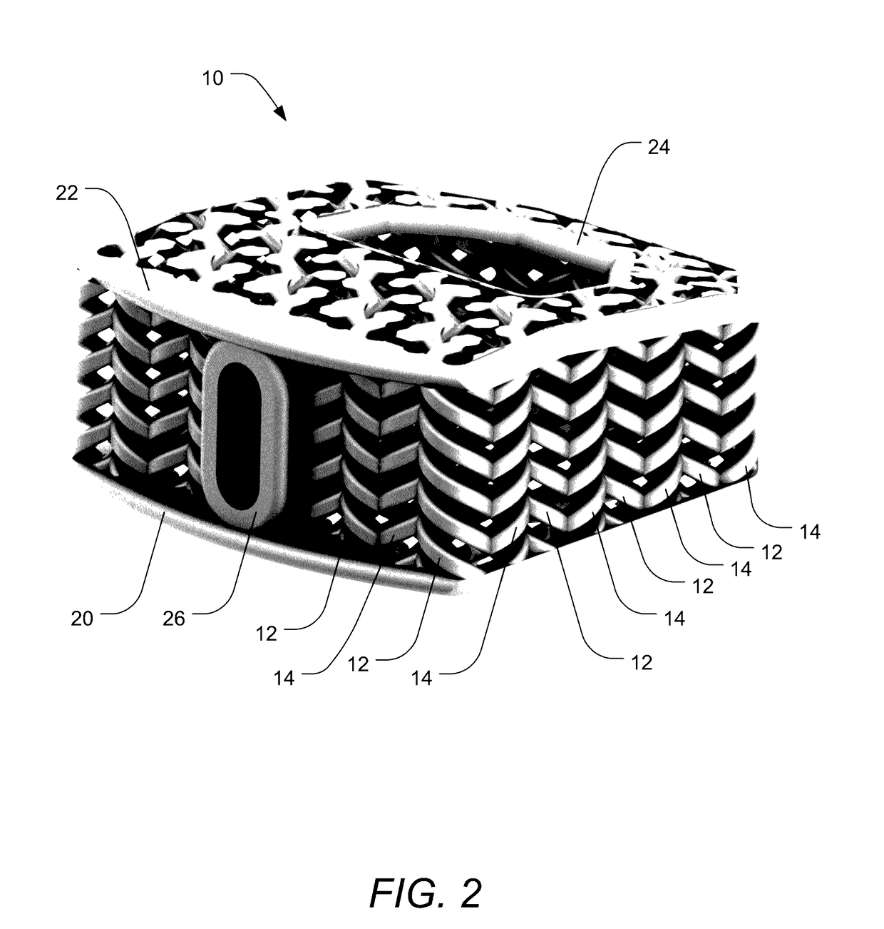
Orthopedic implants, particularly interbody spacers, have a combination of correct pore size and stiffness / flexibility. When the implants have the proper pore size and stiffness, osteocytes are able to properly bridge the pores of the implant and then experience a proper compressive load to stimulate the bone cells to form bone within the pores. An implant includes a body formed of an osteoconductive material and having a stiffness of between 400 megapascals (MPa) and 1,200 MPa. Additionally, the body includes a plurality of pores having an average size of between 150 microns and 600 microns. The pores permit the growth of bone therein. The body is formed of packs of coils which may be formed using an additive manufacturing process and using traditional orthopedic implant materials such as titanium and titanium alloys while still achieving desired stiffness and pore sizes of the implants.

Description

CROSS-REFERENCE TO RELATED APPLICATIONS[0001]This application claims the benefit of U.S. Provisional Application No. 62 / 264,217, filed Dec. 7, 2015, and U.S. Provisional Application No. 62 / 355,789, filed Jun. 28, 2016, each of which is incorporated by reference herein for all it discloses.BACKGROUND OF THE INVENTION[0002]1. Field of the Invention[0003]The present invention relates to spinal fusion implants, and more particularly to a porous interbody spacer having advantageous properties to facilitate support and bone growth into the implant.[0004]2. Background and Related Art[0005]Human bones are generally formed of two types of structural bone tissue: cortical bone and trabecular or cancellous bone. Cortical bone generally forms the outer shell of most bones, and is more dense, harder, stronger, and stiffer than trabecular bone. Trabecular bone is typically found at the ends of long bones proximal to joints, as well as in the interior of vertebrae. Trabecular bone is highly vascul...

Claims


Application Information

Patent Timeline
Patent Type & Authority Applications(United States)
IPC IPC(8): A61F2/44A61F2/00
CPCA61F2/447A61F2/0077A61F2310/00023A61F2002/30154A61F2310/00131A61F2002/30153A61F2002/30146A61F2002/30149A61F2002/0081A61F2002/30568A61F2/4455A61F2002/30289A61F2002/30566A61F2002/30593A61F2002/30784A61F2002/3092A61F2002/3093A61F2002/3097A61F2002/4495
Inventor HALVERSON, PETERHAWKES, DAVID
Owner NEXUS SPINE L L C
Learn More