
Method and device for digital reconstruction of an elementary volume representing a microstructure of composite material

a composite material and microstructure technology, applied in the field of digital reconstruction of representative volume elements, can solve the problems of high fiber volume packing ratio, and low fiber volume packing ratio

Active Publication Date: 2017-06-01
SAFRAN
View PDF1 Cites 9 Cited by
  • Summary
  • Abstract
  • Description
  • Claims
  • Application Information

AI Technical Summary

Benefits of technology

The invention proposes a way to reconstruct the part of a composite material that has a high packing ratio, which is typically greater than 90%. This helps to create a digital representation of the material and predict its mechanical properties. By recreating the random tangling of the fiber chips, the invention achieves this.

Problems solved by technology

The performance of such composite materials depends directly on the tangling of the fiber chips, and suffers from a high degree of variability due to the random nature of the microstructure (or “geometry”) of the composite material at chip scale.
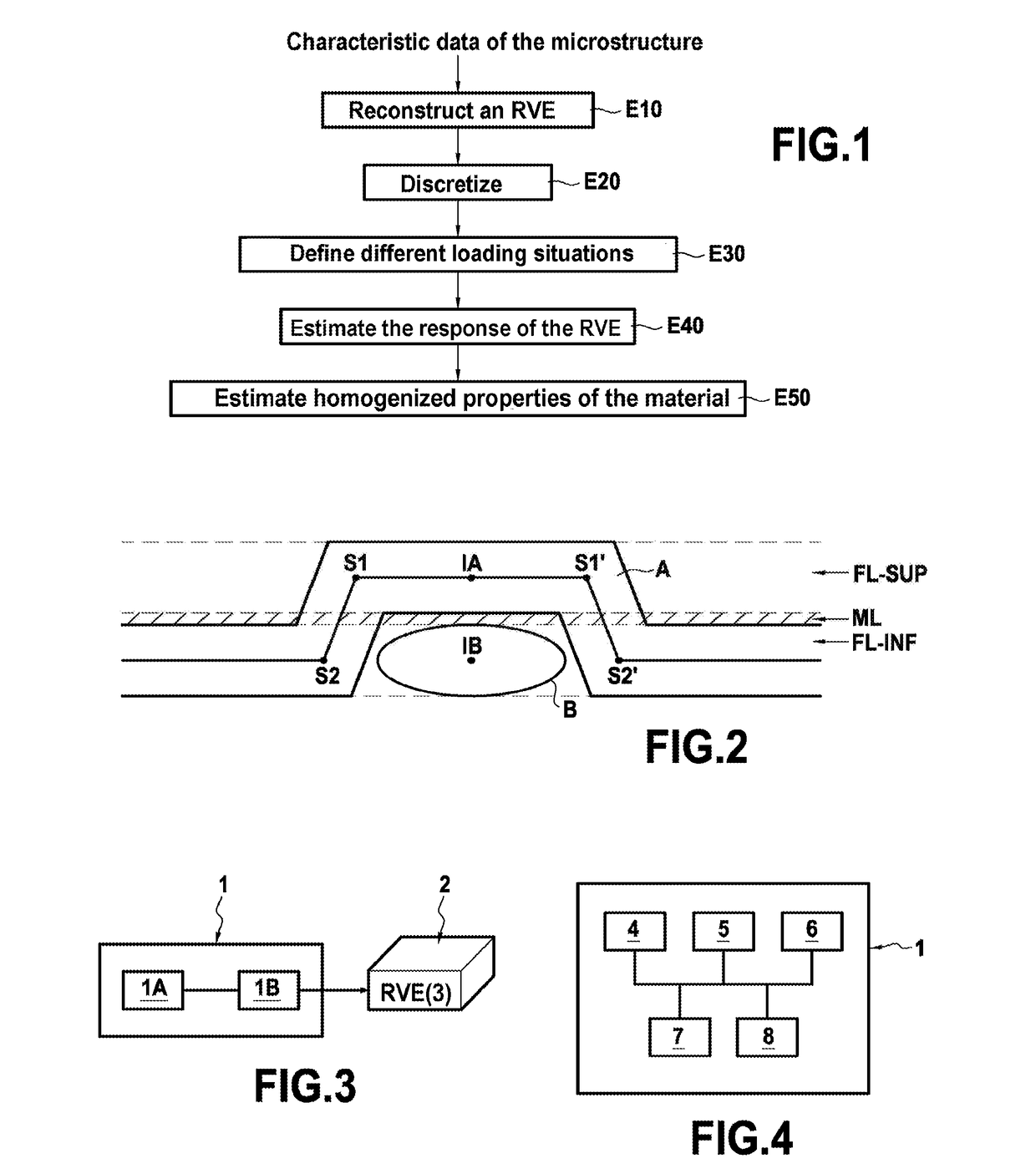
One of the main difficulties with that approach lies in the RVE digital reconstruction step E10 and the discretization step E20, in particular for composite materials such as DFCs (based on discontinuous long fibers) that are fabricated from random tangling of preimpregnated fiber chips and that present a high fiber volume packing ratio.
Although that first method can be implemented quickly, it can nevertheless be understood that the resulting fiber volume packing ratio is very small; typically it does not exceed 40%, which is not representative of reality in the composite materials under consideration.
Nevertheless, such a technique is not pertinent for certain composite materials, and in particular for composite materials having long discontinuous fibers in which the reinforcing fiber chips are of similar sizes relative to one another.
That second method is thus remote from reality and is not directly usable for predicting failure involving interlaminar stresses at the surfaces of the chips, since the method does not enable them to be evaluated.

Method used


Image

  • Method and device for digital reconstruction of an elementary volume representing a microstructure of composite material
  • Method and device for digital reconstruction of an elementary volume representing a microstructure of composite material
  • Method and device for digital reconstruction of an elementary volume representing a microstructure of composite material

Examples


Embodiment Construction

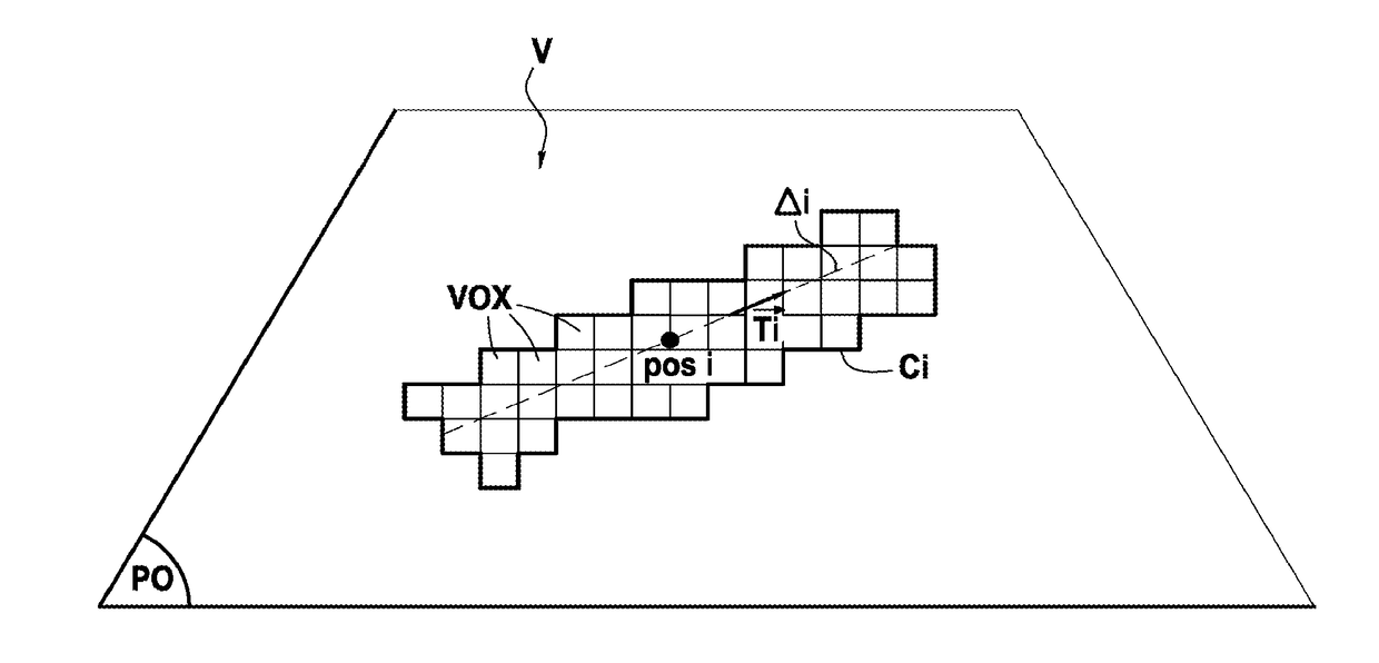
[0082]FIG. 3 shows, in its environment, a device 1 for reconstructing a representative volume element (RVE) 2 of microstructure of a composite material in accordance with a particular embodiment of the invention. In known manner, a representative volume element of a composite material is a geometrical entity that is statistically representative of the microstructure of the composite material, i.e. that models the microstructure.

[0083]In the presently-described example, consideration is given to a composite material 3 of DFC type, in other words having discontinuous long fibers that is made from fiber chips that are randomly tangled and preimpregnated with a thermosetting resin (matrix). By way of example, the chips are chips of glass fiber or of carbon fiber impregnated with a carbon resin, and they are substantially in the shape of rectangular parallelepipeds.

[0084]Nevertheless, the invention is naturally applicable to other composite materials made up of fiber elements preimpregna...


PUM


Abstract

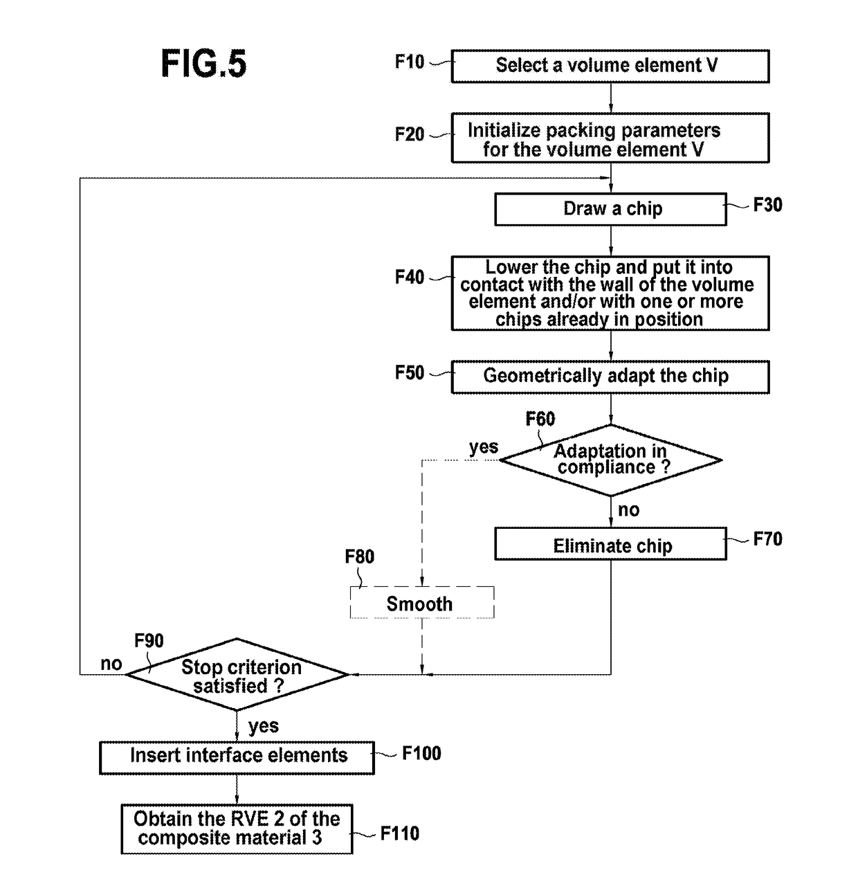
The method including defining a volume element and packing the volume element with digital elements modelling fiber elements of the composite material, and extending longitudinally along a main axis, the packing including associating each digital element with a position in a plane in three-dimensional space and with an orientation of its main axis; and successively positioning each digital element in the volume element in compliance with the position and the orientation that are associated therewith, this positioning including putting the digital element into contact with a wall of the volume element and / or a previously-positioned digital element, and geometrically adapting the digital element to the wall and / or to the previously-positioned element with which it is in contact; a portion of a digital element being subjected to a deformation other than having its longitudinal axis inclined relative to the main axis of the digital element.

Description

BACKGROUND OF THE INVENTION[0001]The invention relates to the general field of digital modelling.[0002]More particularly, it relates to a method of digitally reconstructing a representative volume element (or RVE) of the microstructure of a composite material, such as for example a composite material having discontinuous long fibers (also known as discontinuous fiber composites (DFCs)) manufactured from “chips” of fibers (e.g. of glass, carbon, etc.) tangled together randomly and pre-impregnated with a thermosetting or thermoplastic resin, also known as a “matrix”.[0003]Such composite materials are particularly well adapted to making parts of complex shape (e.g. including ribs or projections), such as those used in particular in the aviation industry or in numerous other mechanical engineering industries. Such parts are fabricated in known manner from preforms that are cut out from a sheet of material made up of tangled fiber chips, and then assembled in a mold where they are subjec...

Claims


Application Information

Patent Timeline
Patent Type & Authority Applications(United States)
IPC IPC(8): G06F17/50
CPCG06F2217/44G06F17/5018G06F30/23G06F2113/26G06T17/10G06T19/20G06F30/00
Inventor TRANQUART, BASTIENMANDEL, ROBIN
Owner SAFRAN
Learn More