
Adjustable Damping Valve Device With A Damping Valve

Active Publication Date: 2017-06-01
ZF FRIEDRICHSHAFEN AG
View PDF1 Cites 10 Cited by
  • Summary
  • Abstract
  • Description
  • Claims
  • Application Information

AI Technical Summary

Benefits of technology

The patent describes a damping valve device that uses a movable element to create a flow passage that allows a damping medium to flow through it. This eliminates the need for the valve to be lifted and allows for easier installation and space-saving. The device also uses a helical spring that is easy to produce and can provide a consistent damping action. The design allows for axial movement between the different parts and ensures a uniform and defined damping function. Overall, the device is simple in construction and economical in space-usage while still providing effective damping performance.

Problems solved by technology

Further, the axial movability of the control element is limited by the valve slide and the valve seat element.
In addition, the axial movability of the valve slide is limited in axial direction by the valve housing and the control element.
The axial movability of the valve seat element is possibly limited by the control element and the valve housing.

Method used


Image

  • Adjustable Damping Valve Device With A Damping Valve
  • Adjustable Damping Valve Device With A Damping Valve
  • Adjustable Damping Valve Device With A Damping Valve

Examples


Embodiment Construction

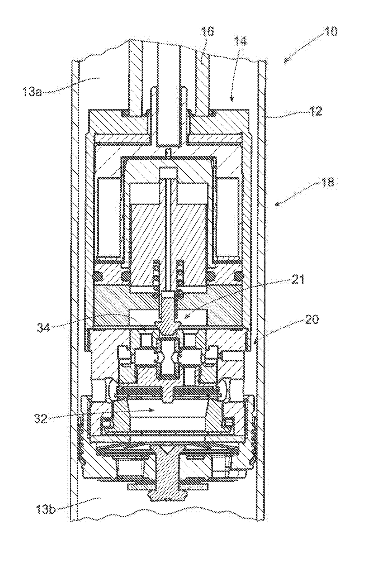
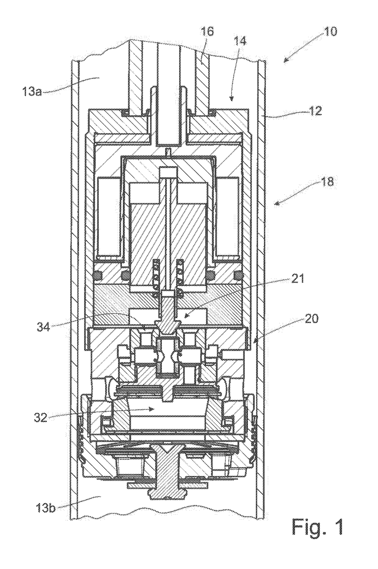
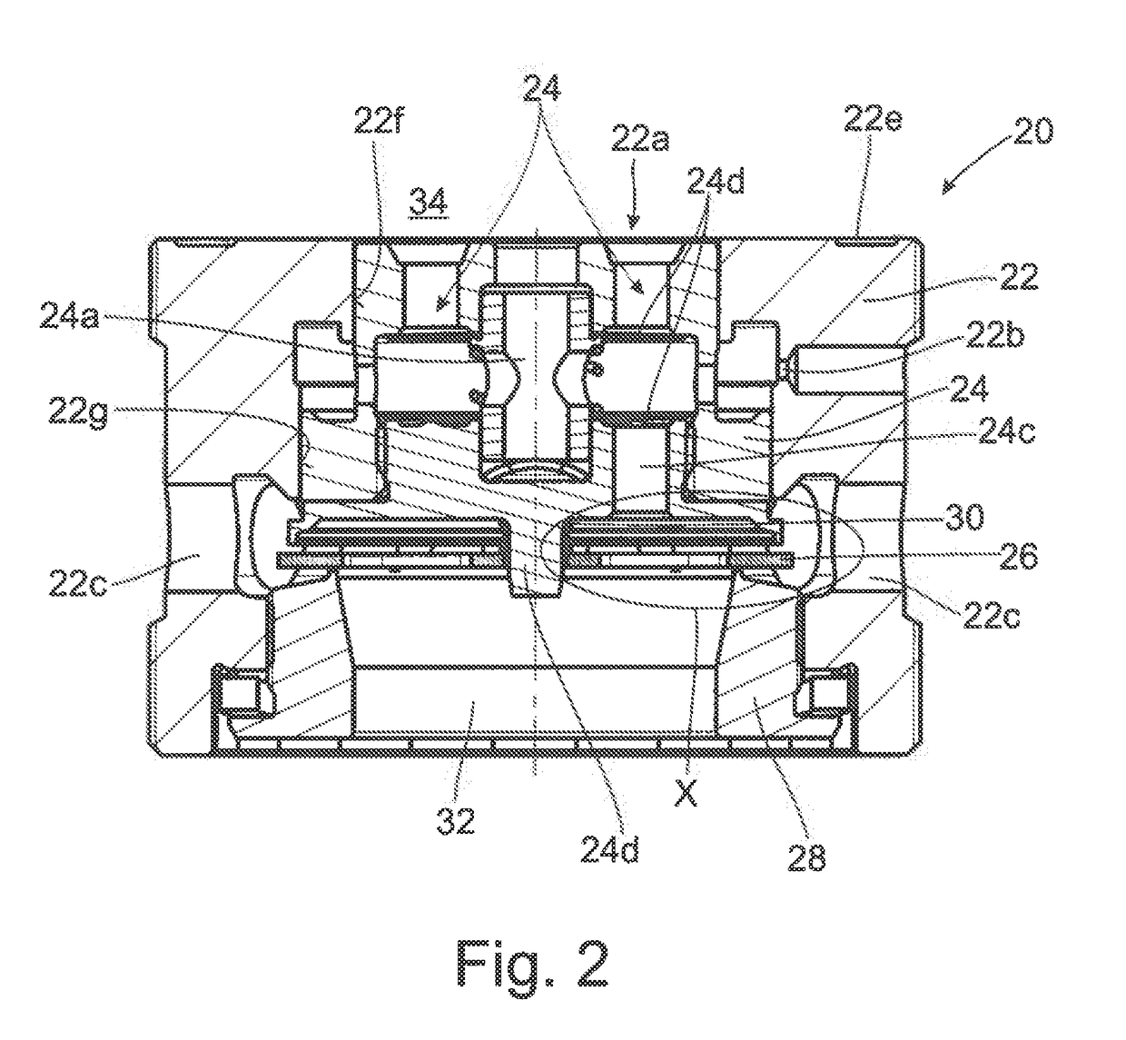
[0036]FIG. 1 shows a vibration damper 10 in which a damping valve device 14 is arranged inside a damper tube 12. Damping valve device 14 is fastened to a piston rod 16. The damping valve device 14 includes an actuator 18 and a damping valve 20. The damping valve 20 is shown again individually in FIG. 2 and in FIG. 3. In addition, the damping valve device 14 divides the damper tube into an upper working space 13a and a lower working space 13b.

[0037]The damping valve comprises a valve housing 22, a valve slide 24, a control element 26, a valve seat element 28 and an elastic element 30. The valve housing 22 is formed in one piece and has a concentrically arranged orifice 22a formed in axial direction. This step-shaped orifice 22a receives, the valve slide 24, the control element 26 and the valve seat element 28. Further, the valve housing 22 has a radially extending choke opening 22b. There is also a plurality of likewise radially extending flow passages 22c in the valve housing 22. F...


PUM


Abstract

An adjustable damping valve device with a damping valve has an elastic element, applies an axial relative force between two elements which are constructed so as to be axially movable relative to the valve housing, or the elastic element applies a relative force between an element of the damping valve, which element is constructed so as to be axially movable relative to the valve housing, and the valve housing, or the elastic element applies a relative force between an element of the damping valve, which element is constructed so as to be axially movable relative to the valve housing, and an element which is constructed so as not to be displaceable relative to the valve housing, so that one of the axially movable elements releases a flow passage for the flow of damping medium through the damping valve at least in a neutral state of the damping valve device.

Description

[0001]The present invention is directed to an adjustable damping valve device with a damping valve having a flow passage at least in a neutral state and to a vibration damper with a damping valve device of this type.BACKGROUND OF THE INVENTION[0002]EP 2 677 194 A2 shows an adjustable damping valve device with an actuator for a vibration damper. A damping valve with a valve housing, a valve slide and a valve seat is disclosed. The valve slide is axially movably arranged in the valve housing. The valve slide rests on the valve seat element, particularly in a neutral state of the damping valve device. Therefore, the valve slide must initially be lifted from its valve seat when the damping valve device operates inside the vibration damper. The mass inertia of the valve slide which must be overcome in order for the valve slide to be lifted from the valve seat for the first time leads to an increase in damping force of the vibration damper. An increase in damping force of this kind is not...

Claims


Application Information

Patent Timeline
IPC IPC(8): F16F9/46F16K15/02B60G13/08F16F9/342F16F9/348
CPCF16F9/469F16F9/342F16F9/348B60G13/08F16F2228/066B60G2500/11B60G2202/24B60G2800/162F16K15/025F16F9/34F16F9/3485F16F9/3481F16F9/3405
Inventor SCHAFFELHOFER, TIMOSAUERBREY, ACHIM
Owner ZF FRIEDRICHSHAFEN AG
Learn More