
Machine cutting torch system

a cutting torch and machine technology, applied in the direction of gas flame welding apparatus, combustion process, lighting and heating apparatus, etc., can solve the problems of gas consumption variability, nozzle blockage during operation, and operator monitoring of gas consumption is a further problem, so as to achieve easy handling, increase life, and the effect of increasing the degree of automation

Active Publication Date: 2017-05-11
GCE HLDG
View PDF4 Cites 4 Cited by
  • Summary
  • Abstract
  • Description
  • Claims
  • Application Information

AI Technical Summary

Benefits of technology

The present invention is a cutting torch system designed to resolve issues of difficulty handling, low automation, short lifetime, excessive spare parts, poor cut quality, and slow cutting performance. The system has been designed for easy handling, higher automation, increased lifetime, savings on spare parts, better cut quality, improved cutting performance, and shorter setting times. Additionally, the system has also been designed to reduce equipment and process costs.

Problems solved by technology

The operator will often also change the nozzle, connected to the cutting torch, due to maintenance requirements or set up changes.
The nozzle often becomes blocked during operation due to spatter and incorrect flame set up.
Monitoring the consumption of gas is a further problem for the operator.
As set up is purely manual, the gas consumption may vary significantly each time the cutting machine is used.
Therefore, it is very challenging to predict the gas consumption and related costs.
An external solution also requires more spare parts, it makes the cutting machine more complicated, and it is necessary to adjust the ignition device to the correct position in order to ensure proper functioning.
Further, external ignition devices are very frequently damaged or destroyed by the cutting process.
Hence, there is more chance of function failure when using an external ignition device.
This leads to an expensive and complex solution which is difficult to control and set up.
Usually, cutting oxygen pressure is not measured at all at the cutting torch itself, which means that exact information about an important process parameter is missing.
Pressure is normally measured at the pressure gauge on the pressure regulator or at the proportional valve inside the cutting machine, which is not sufficiently accurate.
However, the accuracy and life-time of such a solution is too low and its complexity is too high.
Further, it is not always possible to use such an additional gauge.
The lack of exact information about the cutting oxygen pressure prevents simple optimization of the process parameters and causes a lower performance than necessary for the cutting process.
This is a problem since the procedure takes time, and there is a risk of applying an excessive tightening torque, resulting in damages to the connecting thread and the sensitive nozzle surface.
A further problem is associated with adjusting the distance between nozzle and work piece such that the nozzle always is arranged at a correct height.
However, such sensors take up valuable space within in the cutting machine, limit the movements of the cutting torch, are easily damaged by spatter, and often moves out of alignment such that the measured distance differs from the actual distance between nozzle and work piece.
Hence, there are difficulties associated with achieving a correct set up and adjustment of oxygen and fuel gas parameters in response to the actual nozzle used.
Nozzle maintenance is a task often performed with little precision.
Operators use basic skills to clean the nozzle, but if it is done incorrectly it can significantly reduce the performance of the nozzle, and hence the torch, and could lead to safety issues.
For example, if the cutting oxygen channel is opened up incorrectly, an unbalanced flow of oxygen could arise which will lead to a sub-optimal cutting profile and could also lead to a flashback of excess oxygen into the nozzle and cutting torch.

Method used


Image

  • Machine cutting torch system
  • Machine cutting torch system
  • Machine cutting torch system

Examples


Embodiment Construction

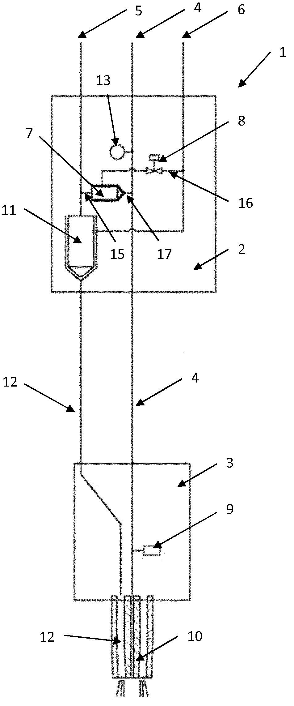
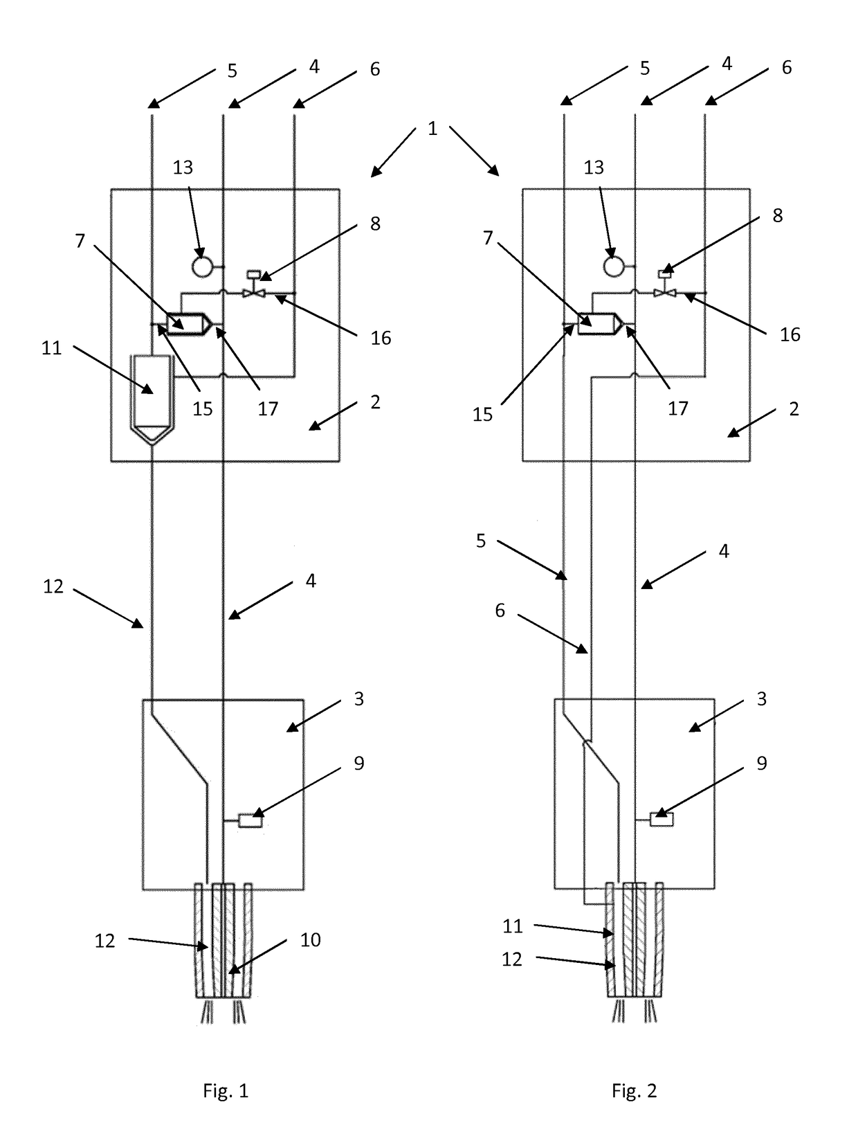
[0056]The invention relates to a combination of innovative systems which generate a new machine cutting torch design philosophy. It comprises a number of highly related elements such as: an ignition mixer for preparation of an ignition gas used together with an internal cooling and cleaning device as disclosed in EP-0,191,741; pressure, temperature, and flow measuring devices; a manually quick-tightened cutting and / or heating nozzle provided with a height control sensor; automatic identification of nozzles and adjustment of oxygen and fuel gas parameters; process control for cleaning, and process automation for cleaning and changing of nozzles.

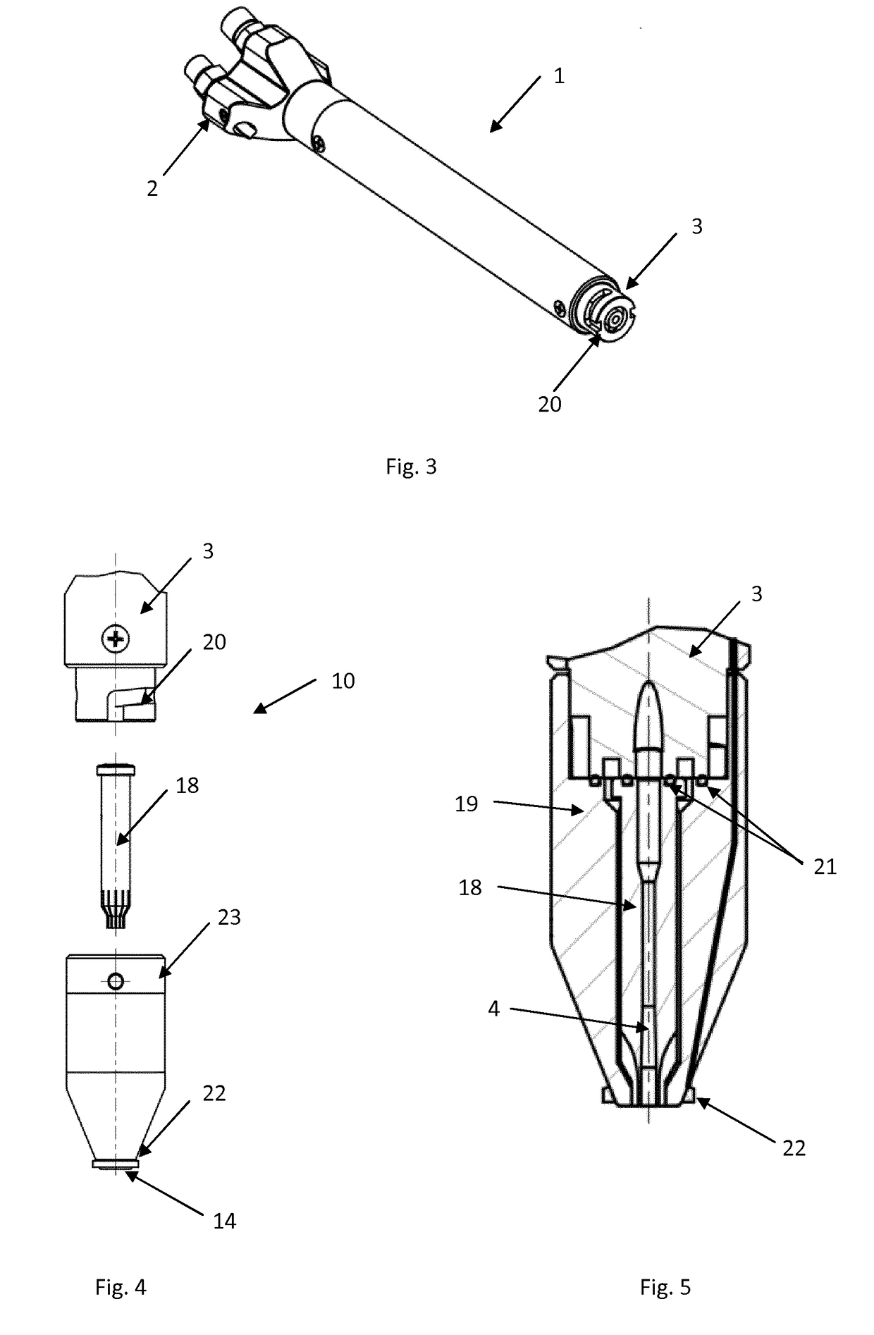
[0057]FIGS. 1 and 2 show two different embodiments of a cutting torch system according to the invention. The cutting torch 1 comprises a body 2 and a head 3. A cutting oxygen channel 4, a heating oxygen channel 5, and a fuel gas channel 6 are connected to an inlet side of the body 2, having one inlet each, and supplies cutting oxygen, heating ...


PUM

PropertyMeasurementUnit
pressureaaaaaaaaaa
flow rateaaaaaaaaaa
temperatureaaaaaaaaaa

Abstract

The present invention relates to a cutting torch system having an ignition mode and a cooling and cleaning mode. The cutting torch system comprises a cutting torch (1) having a cutting oxygen channel (4), a heating oxygen channel (5), and a fuel gas channel (6) The heating oxygen channel (5) and the fuel gas channel (6) are connected to an ignition mixer (7) and a fuel gas shut-off valve (8) is arranged upstream of the ignition mixer (7). The fuel gas shut-off valve (8) is configured to be open in the ignition mode and closed in the cleaning and cooling mode. The ignition mixer (7) is adapted for mixing heating oxygen and fuel gas into an ignition gas and communicating the ignition gas into the cutting oxygen channel (4) in the ignition mode, and for communicating heating oxygen into the cutting oxygen channel (4) in the cleaning and cooling mode.

Description

FIELD OF THE INVENTION[0001]The present invention relates to a cutting torch system comprising at least a cutting torch having a body and a head, a cutting oxygen channel, a heating oxygen channel, and a fuel gas channel, each channel being adapted for supplying a corresponding gas into the body of the cutting torch. The cutting torch system may further comprise an ignition device, a nozzle, a control system, and at least one sensor.BACKGROUND OF THE INVENTION[0002]Cutting metal using an automated machine cutting torch requires significant intervention from the machine operator in order to start and to adjust the cutting process. There is significant skill associated with setting up machine cutting torches, since often no two cutting torches carry the same parameters in set up. The cutting torch requires manual adjustment of oxygen and fuel gas pressure and flow rates during start-up. On each use, the flame of the cutting torch is ignited using an ignition device. Frequently, the ig...

Claims


Application Information

Patent Timeline
Patent Type & Authority Applications(United States)
IPC IPC(8): B23K7/00F23D14/42
CPCF23D14/42B23K7/00
Inventor ROUBICEK, MARTINPOLIVKA, JIRIPEMBERTON, GARETH
Owner GCE HLDG
Learn More