Carbon-based acoustic matching layer and method for producing same

a technology of acoustic impedance and carbon fiber, applied in the direction of mechanical vibration separation, instruments, electrical transducers, etc., can solve the problems of uniform coating thickness, delamination and working temperature, limitation of the amount of change in acoustic impedance in the direction of thickness, etc., to achieve the effect of reducing the amount of change in acoustic impedance, and reducing the amount of loss

Active Publication Date: 2017-05-04
MITSUBISHI PENCIL CO LTD
View PDF2 Cites 5 Cited by
  • Summary
  • Abstract
  • Description
  • Claims
  • Application Information

AI Technical Summary

Benefits of technology

The present invention is related to a carbon-based acoustic matching layer with superior mechanical strength and resistance to chemical and heat damage. By integrating amorphous carbon from adjacent layers, the matching layer increases the amount of change in acoustic impedance in the direction of thickness. The use of a filler particle configuration helps adjust the acoustic impedance to within the desired range. Additionally, the carbon-based acoustic matching layer has excellent processability and can be used as a power supply or conductor for supplying electrical signals. The method of producing the layer ensures efficient carbonization and strengthening of the boundary surfaces between layers, while minimizing bending and delamination.

Problems solved by technology

In the case of laminating materials having different acoustic impedance, since an adhesive is typically used for this purpose, problems with respect to the acoustic impedance of the adhesive layer material, uniformity of coating thickness, delamination and working temperature are thought to occur.
However, according to the technique described in Patent Document 2, since the same filler particles in the form of graphite particles are incorporated into all layers at the same ratio, and changes in acoustic impedance are realized due to differences in porosity, there are limitations on the amount of change in acoustic impedance in the direction of thickness.
In addition, Patent Document 2 does not consider the issues of bending and / or delamination during the course of carbonization and pore formation.

Method used


Image

  • Carbon-based acoustic matching layer and method for producing same
  • Carbon-based acoustic matching layer and method for producing same

Examples


example 1

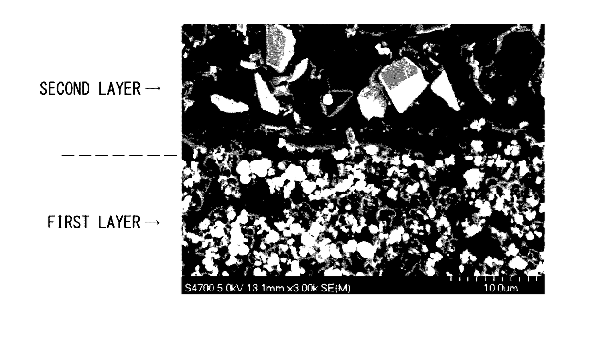
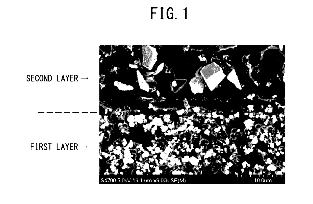
[0072]One part of p-toluenesulfonic acid as a curing agent was added to 30 parts of furan resin (VF-303, Hitachi Chemical Co., Ltd.) as an amorphous carbon source and 70 parts of tungsten carbide (NCWC10, Nikkoshi Co., Ltd., particle size: 1.2 μm) as filler particles, followed by adequately stirring using a high-speed emulsifier / disperser (Model 2.5 Homomixer Mark II, Primix Corp.) and subjecting to a vacuum degassing procedure to prepare a solution for a sheet-like first layer. This solution was poured into a mold having a thickness of 0.7 mm and then cured to obtain a first layer.

[0073]Then, a second layer was laminated onto the resulting sheet-like first layer. More specifically, 1 part of p-toluenesulfonic acid was added to 50 parts of furan resin and 50 parts of titanium carbide (Japan New Metals Co., Ltd., particle size: 1.9 μm) followed by adequately stirring and subjecting to a vacuum degassing procedure to prepare a solution for the second layer. This solution was poured in...

example 2

[0075]One part of p-toluenesulfonic acid as a curing agent was added to 30 parts of a phenol resin (HP3000A, Asahi Yukizai Corp.) and 70 parts of tungsten carbide, followed by adequately stirring and subjecting to a vacuum degassing procedure to prepare a solution for a sheet-like first layer. This solution was coated at a thickness of 30 μm using the No. 542-AB Automatic Film Applicator (Yasuki Seiki Seisakusho, Ltd.) and then cured to obtain a sheet-like first layer.

[0076]Then, a second layer was laminated onto the resulting sheet-like first layer. More specifically, 1 part of p-toluenesulfonic acid was added to 40 parts of furan resin and 60 parts of double carbide (tungsten / titanium carbide) (WC-TiC50 / 50, Japan New Metals Co., Ltd., particle size: 1.0 μm) followed by adequately stirring and subjecting to a vacuum degassing procedure to prepare a solution for the second layer. This solution was coated to a thickness of 30 μm on a sheet molded as the first layer and then cured to ...

example 3

[0079]One part of p-toluenesulfonic acid as a curing agent was added to 50 parts of furan resin and 50 parts of tungsten carbide, followed by adequately stirring and subjecting to a vacuum degassing procedure to prepare a solution for a first layer. This solution was coated at a thickness of 30 μm and then cured to obtain a sheet-like first layer.

[0080]Then, a second layer was laminated onto the resulting sheet-like first layer. More specifically, 1 part of p-toluenesulfonic acid was added to 70 parts of furan resin and 30 parts of titanium oxide (KA-15, Titan Kogyo Ltd., mean particle diameter: 0.5 μm) followed by adequately stirring and subjecting to a vacuum degassing procedure to prepare a solution for the second layer. This solution was coated to a thickness of 30 μm on a sheet molded as the first layer and then cured to obtain a second layer.

[0081]Further, a third sheet was laminated on the resulting sheet-like laminate comprising the first layer and second layer. More specifi...


PUM

PropertyMeasurementUnit
particle sizeaaaaaaaaaa
thicknessaaaaaaaaaa
particle sizeaaaaaaaaaa

Abstract

Provided are: a carbonaceous acoustic matching layer which exhibits satisfactory mechanical strength, in which losses at a layer interface are suppressed as far as possible and in which the degree of variation in acoustic impedance in the thickness direction can be increased; and a method for producing same. The carbonaceous acoustic matching layer is obtained by dispersing filler particles, which are selected on the basis of the desired acoustic impedance of each layer, in a resin such as a furan resin, a phenol resin or a vinyl chloride resin, curing, laminating, and then carbonizing the resin by heating in a non-oxidizing atmosphere, amorphous carbon, which is obtained by the resin carbonization, is integrated across all the layers. The blending proportion of the filler particles is decided so that the difference in coefficient of linear contraction caused by the carbonization is at a minimum between adjacent layers.

Description

TECHNICAL FIELD[0001]The present invention relates to an acoustic matching layer and a method for producing the same, and this acoustic matching layer is suitable as an acoustic member used in, for example, medical ultrasonic contact probes or industrial ultrasonic flaw detection probes.BACKGROUND ART[0002]In ultrasonic probes used as ultrasonic contact probes and ultrasonic flaw detection probes, acoustic impedance is an important factor for ensuring that the vibrations from a lead zirconate titanate (PZT) or other piezoelectric element are allowed to propagate efficiently or that vibrations are efficiently received from a subject. Therefore, materials are required in which the acoustic impedance thereof is roughly intermediate to that of the piezoelectric element and subject, and in recent years, configurations have been proposed that attempt to widen bandwidth and increase sensitivity of ultrasonic waves using multilayered acoustic matching layers.[0003]In the case of laminating ...

Claims


Application Information

Patent Timeline
Patent Type & Authority Applications(United States)
IPC IPC(8): G10K11/168B32B9/00B32B9/04B32B7/02
CPCG10K11/168B32B7/02B32B2307/102B32B9/04G10K11/04B32B9/007G10K11/02B06B2201/76H04R17/00H04R31/00
Inventor OONO, TOSHIKISATAKE, ATSUNORISUZUKI, TAKESHI
Owner MITSUBISHI PENCIL CO LTD
Why Eureka
Try Eureka