
Hot melt adhesive

Active Publication Date: 2017-02-23
MORESCO
View PDF6 Cites 3 Cited by
  • Summary
  • Abstract
  • Description
  • Claims
  • Application Information

AI Technical Summary

Benefits of technology

The present invention provides a hot melt adhesive that has excellent adhesiveness in a wet state and is long-term stable and easy to apply.

Problems solved by technology

Where such hot melt adhesives are used in the field where the probability of contact with moisture is high, the adhesion between the constituent materials, for example, when the products are used, cannot be maintained, and the products themselves can collapse.
However, where the nozzle diameter of the coating apparatus is reduced and the flow velocity of the molten hot melt adhesive is increased, the flow of the hot melt adhesive inside the nozzle becomes unstable and uniform coating tends to be difficult to perform.
In particular, where the uniformity of viscoelasticity of the hot melt adhesive decreases, the pressure or flow velocity inside the nozzle changes abruptly and the hot melt adhesive cannot be sufficiently deflected or the hot melt adhesive is scattered, thereby causing blockage, and the coating shape of the hot melt adhesive can change abruptly.
Since the deterioration of coating ability, such as the abrupt variation of the coating shape, can also degraded the adhesiveness.

Method used


Image

  • Hot melt adhesive
  • Hot melt adhesive

Examples


manufacturing example 1

Acid-Modified Tackifier 1

[0099]A total of 750 g of a hydrogenated aromatic modified terpene resin (CLEARON K4100, manufactured by YASUHARA CHEMICAL CO., LTD.: softening point 100° C.) was loaded into a stainless steel (SUS) reaction kettle and melted at 170° C. A nitrogen atmosphere was then created in the reaction kettle and 22.5 g of anhydrous maleic acid, 5 g of dicumyl peroxide, and 22.5 g of butyl methacrylate were dropped for 1 h into the melt in the reaction kettle. After the dropping was completed, stirring was conducted for 30 min at 170° C., and the reaction kettle was then depressurized, thereby removing, over 1 h, the unreacted matter and low-molecular compounds produced by the decomposition of dicumyl peroxide. As a result, a light-yellow solid matter was obtained. This solid matter was a hydrogenated aromatic modified terpene resin modified by anhydrous maleic acid and butyl methacrylate (acid-modified tackifier 1). The obtained acid-modified tackifier 1 had a melt vis...

manufacturing example 2

Acid-Modified Tackifier 2

[0100]An acid-modified tackifier 2 was manufactured in the same manner as in Manufacturing Example 1, except that a hydrogenated terpene resin (CLEARON P115, manufactured by YASUHARA CHEMICAL CO., LTD.: softening point 115° C.) was used instead of the hydrogenated aromatic modified terpene resin. The acid-modified tackifier 2 was a hydrogenated terpene resin modified by anhydrous maleic acid and butyl methacrylate. The obtained acid-modified tackifier 2 had a melt viscosity of 3,200 mPa·s at 140° C. and a weight-average molecular weight of 1,120.

manufacturing example 3

Acid-Modified Tackifier 3

[0101]An acid-modified tackifier 3 was manufactured in the same manner as in Manufacturing Example 1, except that a hydrogenated alicyclic petroleum resin (ARKON M-100, manufactured by Arakawa Chemical Industries, Ltd.: softening point 100° C.) was used instead of the hydrogenated aromatic modified terpene resin. The acid-modified tackifier 3 was a hydrogenated alicyclic petroleum resin modified by anhydrous maleic acid and butyl methacrylate. The obtained acid-modified tackifier 3 had a melt viscosity of 3,700 mPa·s at 140° C. and a weight-average molecular weight of 1,170.


PUM

PropertyMeasurementUnit
Percent by massaaaaaaaaaa

Abstract

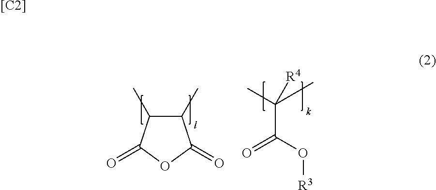
One aspect of the present invention resides in a hot melt adhesive including a thermoplastic polymer and a tackifier, wherein the tackifier includes an acid-modified tackifier that is modified by at least one of maleic acid and maleic anhydride, and by at least one selected from the group consisting of acrylic acid, methacrylic acid, an acrylic acid ester, and a methacrylic acid ester.

Description

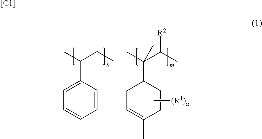
TECHNICAL FIELD[0001]The present invention relates to a hot melt adhesive.BACKGROUND ART[0002]Hot melt adhesives are melted by heating and coated on adherends which are to be bonded, the adherends are then brought into contact with each other, with the melted hot melt adhesive being interposed therebetween, and held in this state, such that the adherends are bonded together. Such hot melt adhesives are used in a variety of fields, for example, in the field of packaging articles such as cardboards and small boxes, the field of sanitary materials such as disposable diapers and sanitary supplies, binding field, plywood field, woodworking field, automotive filed, field of home appliances, and field of household articles.[0003]As mentioned hereinabove, hot melt adhesives are coated after being melted by heating. Therefore, no solvent is required therefor. For this reason, hot melt adhesives have been advantageously used, for example, in the field of sanitary materials as adhesives which ...

Claims


Application Information

Patent Timeline
IPC IPC(8): C09J11/08C09J153/02
CPCC09J153/02C09J11/08C09J151/00
Inventor ICHIKAWA, HISASHIKUROKAWA, HIROSHISAMITSU, MAKIFUKUDA, KATSUHITO
Owner MORESCO
Learn More