Submicron-sized particles including aluminum

a technology of aluminum oxide and submicron particles, which is applied in the field of multi-layer particle production, can solve the problems of inhomogeneity between silicon carbide and aluminium oxide or aluminium in the obtained material, and it is difficult to obtain a material of homogeneous microstructure or nanostructure, so as to improve the control of the homogeneity of distribution and thickness of the layer, and complete the flexibility of the process

Inactive Publication Date: 2016-12-29
NANOMAKERS
View PDF5 Cites 2 Cited by
  • Summary
  • Abstract
  • Description
  • Claims
  • Application Information

AI Technical Summary

Benefits of technology

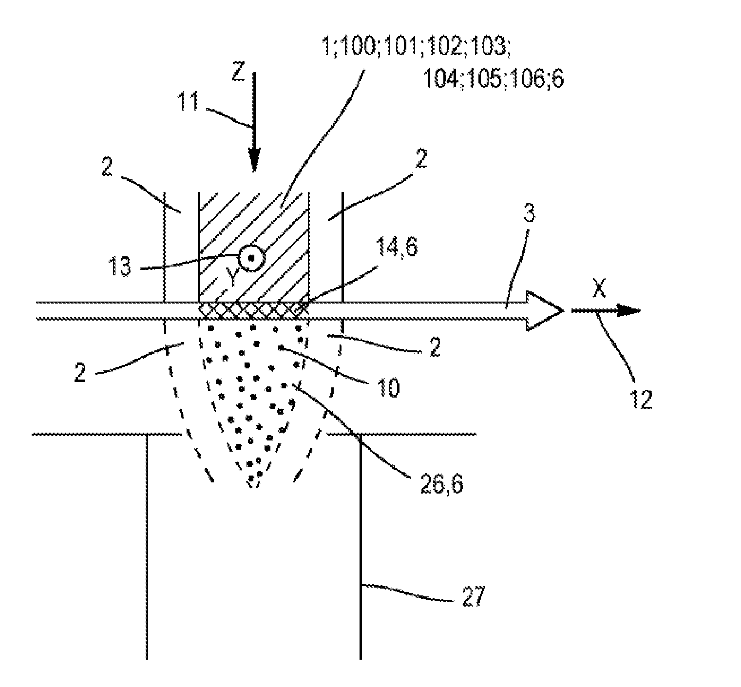
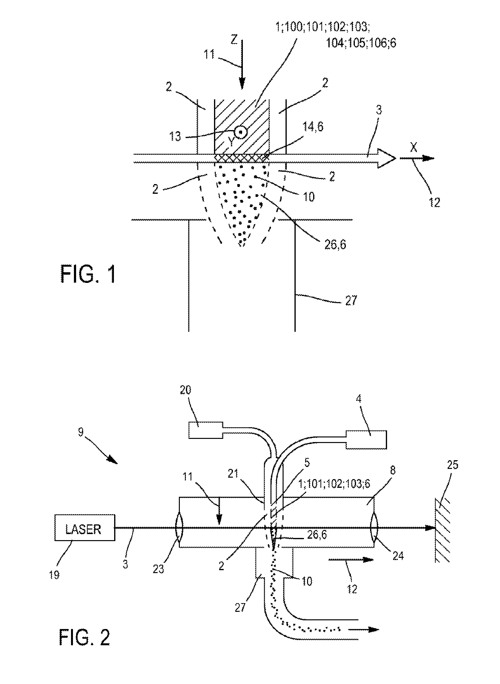
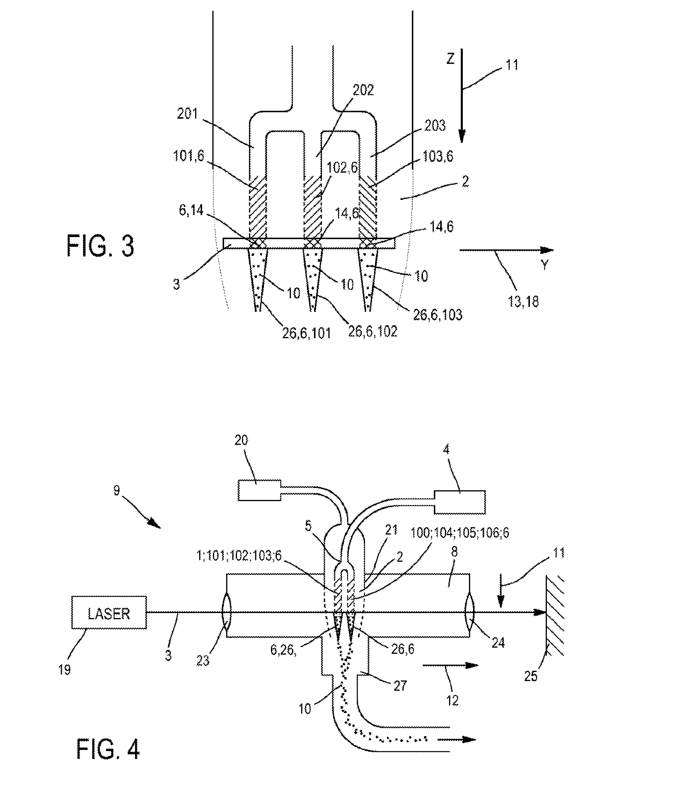
[0025]The second chemical element may be introduced into the chamber in a peripheral gas stream surrounding each reaction stream, emitted from several points distributed along a closed curve surrounding each reaction stream and propagating in the direction of each reaction stream. The second chemical element is preferably introduced into the chamber in the peripheral gas stream after the interaction zone of each reaction stream with the radiation beam. These arrangements make it possible to maintain complete flexibility of the process, allowing the particle cores to be produced, and in particular full capacity for producing cores of adjustable size. These embodiments significantly improve control of the homogeneity of distribution and thickness of the layer of second element on each particle core.

Problems solved by technology

There may be problems of inhomogeneity between the silicon carbide and the aluminium oxide or the aluminium in the material obtained, in particular arising from difficulties in mixing two powders, at least one of which is a nanometric powder.
These difficulties arise from the agglomeration forces, which are greater in the case of nanometric powders, and which make it difficult to obtain a material of homogeneous microstructure or nanostructure when a powder of nanometric size is used.
Moreover, there may be problems of binding or of chemical compatibility between the particles of the two powders, making it necessary to carry out chemical or thermal post-treatments on the powders before using them.

Method used


Image

  • Submicron-sized particles including aluminum
  • Submicron-sized particles including aluminum
  • Submicron-sized particles including aluminum

Examples


example 2

Third Embodiment of the Process According to the Invention; Core 15 Comprising Non-Oxidized Silicon Carbide (SiC); Layer 16 of Aluminium

[0196]Example 2 will only be described where it differs from example 1. Example 2 is identical to example 1, except that in example 2 the surface density of incident energy is 1500 W per square centimetre and the reagent in each reaction stream is a mixture of:[0197]gaseous silane (SiH4) not mixed with oxidizing agents or with oxygen atoms or with molecules comprising oxygen atoms, and[0198]gaseous C2H2 not mixed with oxidizing agents or with oxygen atoms or with molecules comprising oxygen atoms so that the particle cores 15 comprise (preferably consist of) silicon carbide (SiC), preferably not oxidized.

[0199]Particles Obtained

[0200]Particles according to the first example were manufactured according to example 1 and example 2 with the third embodiment of device 9 alone (i.e. with the third embodiment of the process according to the invention). The...


PUM

PropertyMeasurementUnit
thicknessaaaaaaaaaa
diameteraaaaaaaaaa
diameteraaaaaaaaaa

Abstract

A method for producing particles, includes the following steps: introducing into a reaction chamber at least one reaction flow including a first chemical element (typically silicon) and propagating in a flow direction; projecting a ray beam through the reaction chamber, intersecting each reaction flow in an reaction flow interaction area, in order to form, in each reaction flow, the cores of particles including the first chemical element, and introducing, in the reaction chamber, a second chemical element, interacting with each reaction flow in order to cover the cores of particles with a layer including the second chemical element. Each reaction flow is preferably free of an agent oxidizing the first chemical element.

Description

TECHNICAL FIELD[0001]The present invention relates to a process for producing multilayer particles (typically a core layer covered with an upper layer), typically by laser pyrolysis. It also relates to an associated device.[0002]Such a process enables a user for example to manufacture submicron particles of silicon or silicon carbide, each covered with a layer of aluminium or aluminium oxide.PRIOR ART[0003]Processes for producing a material are known in which the raw material used is a mixture of two powders, at least one of which is characterized by an average grain size in the nanometric range:[0004]a powder of particles of a first type, for example of silicon carbide, and[0005]a powder of particles of a second type, which are particles of aluminium or aluminium oxide.[0006]Then the whole is heated to a moderate temperature, optionally under pressure, without bringing it to the melting temperature (“sintering” process), in order to obtain a dense nanostructured material.[0007]Ther...

Claims


Application Information

Patent Timeline
Patent Type & Authority Applications(United States)
IPC IPC(8): C01B33/029B01J4/00B01J19/08C01B31/36C09C1/28
CPCC01B33/029C01B31/36B01J2219/0875B01J19/081B01J4/001C09C1/28B01J4/002B01J4/004B01J12/005B01J13/04B01J19/24B01J2219/00139C01B32/956C01B32/963C01B33/027C01P2004/62C01P2004/64C01P2004/86C09C1/30C09C1/3045B01J19/121
Inventor TENEGAL, FRANCOISREAU, ADRIEN
Owner NANOMAKERS
Why Eureka
Try Eureka