Cu Core Ball, Solder Paste, Formed Solder, Cu Core Column, and Solder Joint

a technology of solder paste and solder joint, which is applied in the direction of soldering apparatus, semiconductor/solid-state device details, superimposed coating process, etc., can solve the problems of short circuit between the electrodes and hinder the high-density packaging, so as to reduce the effect of reducing the strength and strength against heat cycl

Active Publication Date: 2016-12-22
SENJU METAL IND CO LTD
View PDF3 Cites 8 Cited by
  • Summary
  • Abstract
  • Description
  • Claims
  • Application Information

AI Technical Summary

Benefits of technology

The present invention is able to achieve both desired levels in dropping strength and strength against heat cycle when using a solder ball made from an Ag-free solder alloy. This is compared to a solder ball made from an Ag-containing solder alloy, which has reduced strength against heat cycle. The same applies to a Cu core ball and a Cu core column made from the same two solder alloys. Overall, the present invention demonstrates how to achieve desired levels of strength and resistance to heat cycle when using certain solder materials.

Problems solved by technology

However, when BGA is applied to semiconductor packages to which the three dimensional high density mounting structure is applied, solder balls are collapsed by the self-weight of the semiconductor packages, so that short circuits occur between the electrodes.
This may hinder the high-density packaging.

Method used


Image

  • Cu Core Ball, Solder Paste, Formed Solder, Cu Core Column, and Solder Joint
  • Cu Core Ball, Solder Paste, Formed Solder, Cu Core Column, and Solder Joint
  • Cu Core Ball, Solder Paste, Formed Solder, Cu Core Column, and Solder Joint

Examples


Embodiment Construction

[0029]The following will describe an embodiment below more in detail in which this invention is applied to a Cu core ball. In the present description, the units relating the composition of the Cu core ball (ppm, ppb, and %) represent the proportions with reference to the mass (mass ppm, mass ppb, and % by mass), unless otherwise specified.

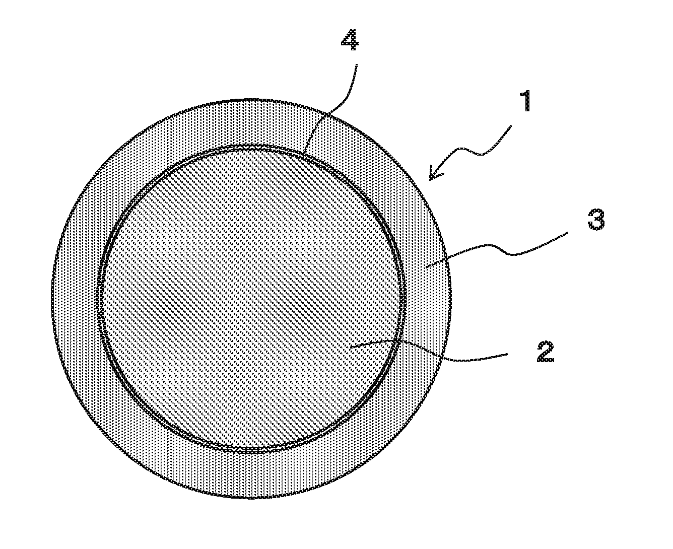
[0030]FIG. 1 is a schematically cross sectional view of a Cu core ball according to an embodiment of the present invention for showing a configuration thereof. The Cu core ball 1 of the present embodiment includes a Cu ball 2, and a solder layer 3 covering the Cu ball.

[0031]The solder layer 3 is made of an Ag-free solder alloy composed of not less than 0.1% through not more than 3.0% of Cu, the remainder being Sn, and the solder layer 3 is formed by subjecting the surface of the Cu ball 2 to solder plating. The Cu ball 2 is made of Cu or a Cu alloy containing 50% or more of Cu.

[0032]In the Cu core ball 1, a diffusion prevention layer 4 is formed be...


PUM

PropertyMeasurementUnit
Fractionaaaaaaaaaa
Fractionaaaaaaaaaa
Fractionaaaaaaaaaa

Abstract

Provided are a Cu core ball and a cu core column, which achieve dropping strength and strength against heat cycle. The Cu core ball (1) contains a Cu ball (2) made of Cu or a Cu alloy and a solder layer (3) which is made of a solder alloy composed of Sn and Cu and covers the Cu ball (2). The solder layer (3) contains not less than 0.1% through not more than 3.0% of Cu and the remainder is composed of Sn and impurities.

Description

TECHNICAL FIELD[0001]The present invention relates to a Cu core ball in which a Cu ball is covered by a solder alloy, a solder paste using the Cu core ball, a formed solder using the Cu core ball, and a solder joint using the Cu core ball and also relates to a Cu core column and a solder joint using the Cu core column.BACKGROUND ART[0002]In recent years, with the development of small-size information equipment, rapid miniaturization has been advanced in electronic components mounted thereon. In order to cope with narrowing of connection terminals and reduction of mounting areas according to downsizing requirement, a ball grid array (hereinafter, referred to as “BGA”) in which electrodes are arranged on the rear surface thereof is applied to the electronic component.[0003]The electronic component to which BGA is applied is, for example, a semiconductor package. In the semiconductor package, a semiconductor chip having electrodes are sealed with any resin. Solder bumps are formed on t...

Claims


Application Information

Patent Timeline
IPC IPC(8): B23K35/30C22C9/00C22C13/00B23K35/02B23K35/26B22F1/00B22F1/065B22F1/17
CPCB23K35/302B23K35/025C22C9/00B23K35/262C22C13/00B23K35/0222B22F1/00B23K35/26B23K35/22C22C1/0483H01L24/13H01L2225/06517H01L2924/15311H01L2225/06513H01L2224/13411C25D3/60H01L23/556H01L24/81H01L2224/13294H01L2224/13347H01L2224/81075H01L2224/81211H01L2224/81395H01L2224/81444H01L2224/81447H01L2224/81815H01L2224/81048H01L2224/13455H01L2224/13457H01L2224/13311H01L2224/11825H01L2224/13561H01L24/05H01L24/11H01L24/16H05K3/3463H01L2224/0401H01L2224/05647H01L2224/13013H01L2224/13014H01L2224/13016H01L2224/13017H01L2224/13147H01L2224/13611H01L2224/13655H01L2224/13657H01L2224/16145H01L2224/16227H01L2224/81024H05K2201/0218H01L2224/13012C25D7/00H01L2924/351C23C28/021B22F1/065B22F1/17H01L2924/013H01L2924/01029H01L2924/00014H01L2924/0105H01L2924/01051H01L2924/01083H01L2924/0103H01L2924/01026H01L2924/01013H01L2924/01033H01L2924/01047H01L2924/01049H01L2924/01048H01L2924/01028H01L2924/01082H01L2924/01044H01L2924/01015H01L2924/01016H01L2924/01092H01L2924/00012H01L2924/0109H01L2924/01203H01L2924/01204B23K35/0244
Inventor HATTORI, TAKAHIROSOMA, DAISUKEROPPONGI, TAKAHIROSATO, ISAMU
Owner SENJU METAL IND CO LTD
Why Eureka
Try Eureka