
Hot press formed parts having excellent powdering resistance during hot press forming, and method of manufacturing the same

a technology of hot press forming and powdering resistance, which is applied in the direction of manufacturing tools, heat treatment equipment, furnaces, etc., can solve the problems of brittleness of the plated layer and difficulty in continuous hot press forming

Active Publication Date: 2016-12-15
POHANG IRON & STEEL CO LTD
View PDF1 Cites 19 Cited by
  • Summary
  • Abstract
  • Description
  • Claims
  • Application Information

AI Technical Summary

Benefits of technology

This patent is about a new way of making a part called an HPF, which is used in hot press forming. The new method optimizes the thickness of a layer made of a combination of aluminum and iron (often called an "alloyed layer") to prevent the plating layer from detaching and sticking to the surface of the hot press during the forming process. This results in better quality and more reliable parts. The patent discusses a specific technique that involves controlling the percentage of a specific phase called tau in the plating layer, as well as adding certain elements like silicon and chromium to the plitting layer. Overall, this patent provides a way to make better HPF parts, which can improve the efficiency and quality of hot press forming.

Problems solved by technology

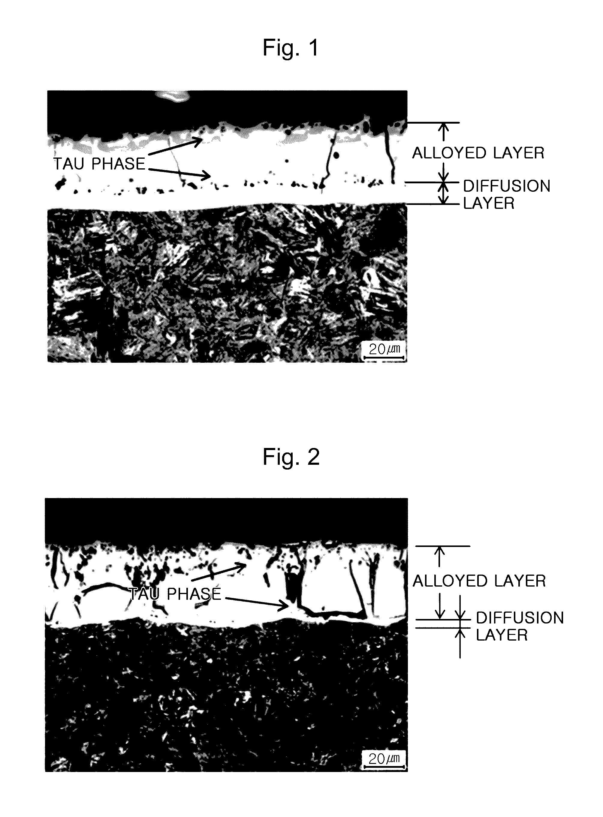
However, because the alloyed layer formed uppermost in the plated layer has brittleness as compared to the diffusion layer, the alloyed layer may be detached from the plated layer during hot press forming and may be attached to a pressing side.
Therefore, this disadvantage makes continuous hot press forming difficult.
Namely, if the Al plated material is hot press formed by heating thereof in a heating furnace at a temperature of 900° C. to 930° C., the plated layer may be detached from a region of high surface friction, and at this time, an overall alloyed layer or a portion thereof may be detached from the region of high surface friction, and therefore, there may be a problem in that the detached plated layer may be attached to the surface of a hot press forming mold.

Method used


Image

  • Hot press formed parts having excellent powdering resistance during hot press forming, and method of manufacturing the same

Examples


example

[0111]First of all, a cold rolled steel sheet in a thickness of 1.4 mm having a composition of 0.227C-0.26Si-1.18Mn-0.014P-0.0024S-0.035A1-0.183Cr-0.034 Ti-0.0023B-0.0040N by wt % was prepared, and oils and contaminants of the surface of the cold rolled steel sheet were removed by washing.

[0112]After heating the cold rolled steel sheet at 760° C., the steel sheet was immersed in a plating bath maintained at 660° C. to form a hot dip aluminum plated layer on the steel sheet. At this time, in the plating bath, other than Al, a Si content was changed to 8% to 11%, and an Fe content was evaluated within a range of 1.7% to 2.5%. Then, as described above, the plated steel sheet where the hot dip aluminum plated layer is formed was cooled, and at this time, the cooling speed of Example 1, Example 2, Example 3, Comparative Example 1, and Comparative Example 2 was controlled to 15° C. / s, 35° C. / s, 45° C. / s, 14° C. / s and 12° C. / s, respectively, in the following Table 1.

[0113]Then, as shown in...


PUM

PropertyMeasurementUnit
thicknessaaaaaaaaaa
temperatureaaaaaaaaaa

Abstract

Provided is a hot press-formed (HPF) member with excellent powdering resistance at the time of press forming. The HPF member includes a hot-dip coating layer containing Al on a surface of a base steel sheet. The base steel sheet includes, based on wt %, 0.18-0.25% of C, 0.1-1.0% of Si, 0.9-1.5% of Mn, 0.03% or less of P, 0.01% or less of S, 0.01-0.05% of Al, 0.05-0.5% of Cr, 0.01-0.05% of Ti, 0.001-0.005% of B, 0.009% or less of N, the balance Fe, and the other impurities. The hot-dip coating layer comprises a soft diffusion layer and a hard alloy layer. The alloy layer has a Tau phase in the range of 10-30%, in terms of area percent.

Description

CROSS-REFERENCE TO RELATED APPLICATION[0001]This application is a continuation of PCT Patent Application No. PCT / KR2015 / 004321 filed on Apr. 29, 2015, which claims priority to and the benefit of Korean Patent Application No. 10-2014-0189096 filed on Dec. 24, 2014, and the entire disclosures of which are incorporated herein by reference.TECHNICAL FIELD[0002]The present disclosure relates to manufacturing a Hot Press Forming (HPF) part having an aluminum plated layer on the surface thereof, and more specifically, to an HPF part having excellent powdering resistance during press forming by minimizing destruction and powdering of a plated layer during hot press forming, and a method of manufacturing the same.BACKGROUND ART[0003]An aluminum plated steel sheet for Hot Press Forming (HPF) is generally prepared by immersing a steel sheet having a high degree of hardenability in a plating bath containing a plating solution based on Al for plating, and then the plated steel sheet having an Al...

Claims


Application Information

Patent Timeline
Patent Type & Authority Applications(United States)
IPC IPC(8): C21D9/46C23C2/40C23C2/28C22F1/043C22C38/32B32B15/01C22C38/06C22C38/04C22C38/02C22C38/00C21D8/02C23C2/12C22C38/28
CPCC21D9/46B32B15/012C23C2/40C23C2/285C22F1/043C22C38/32C22C38/28C22C38/06C22C38/04C22C38/02C22C38/002C22C38/001C21D8/0236C21D8/0226C23C2/12Y10T428/12764Y10T428/12757Y10T428/264Y10T428/1275Y10T428/12972Y10T428/2495Y10T428/263Y10T428/265Y10T428/24967Y10T428/12979C23C2/29C22C38/38
Inventor SOHN, IL-RYOUNGBAE, DAE-CHULKIM, HEUNG-YUN
Owner POHANG IRON & STEEL CO LTD
Learn More