Coforming Processes and Forming Boxes Used Therein

a technology of forming boxes and coforming processes, which is applied in the direction of filament/thread forming, filament chemical after-treatment, fibre treatment, etc., can solve the problems of reducing or stalled flow within the forming box, and achieves the reduction of the volume of upward flow, reducing the ratio of lc/ls, and reducing the volume of separated

Active Publication Date: 2016-12-08
THE PROCTER & GAMBLE COMPANY
View PDF5 Cites 65 Cited by
  • Summary
  • Abstract
  • Description
  • Claims
  • Application Information

AI Technical Summary

Benefits of technology

[0012]One solution to the problem identified above with respect to known coforming processes and known forming boxes is to increase the stability of the coforming process by utilizing a forming box within which two or more separate materials, such as filaments and pulp fibers, are commingled in a non-perpendicular fashion, for example in a non-90° angle, such as an angle of less than 90° and / or less than 85° and / or less than 75° and / or less than 45° and / or less than 30° and / or to about 0° and / or to about 10° and / or to about 25°.
[0013]Angling the introduction of two or more separate materials (solid additives, liquid, continuous, or atomized) through two or more material inlets together at an angle of less than 90° mitigates this effect, especially at higher momentum ratios between the materials (M×V). Another problem that is corrected by this design is the minimization of separated or stalled flow within the forming box (coform box). This results in more even weight distribution and improved sheet formation.
[0017]3. Maximizing heat transfer in and / or out of jets while minimizing mass flow rates in quenching streams.
[0019]With respect to 2 above, proper design of the coform box according to the present invention will allow for the minimization of stalls and / or zones of separated flow, which are particularly problematic in particle laden flow. Again referring to FIG. 4B, minimizing Ls reduces the volume of upward flow associated with the center section of the coform box. In addition, minimizing the ratio of Lc / Ls will reduce the volume of separated flow subsequent to the introduction of streams and just prior to deposition of the material contained in the coform box upon the formaminous surface. In addition, when viewed in cross section, as in FIGS. 4A and 4B, the walls of the coform box should be designed in accordance with aerodynamic principles. Radiuses between different surfaces should be maximized. In the event that the sidewalls in the chutes are divergent and creating a diffuser, it should be designed so that the flow does not separate from one or both walls. Additionally, the coform box should be designed such that the length of Lc is appropriate to the ratio of mass flow rates and length of dimension Lp, such that a flow separation does not occur in the lower box while also not overly constricting the flow exiting the box, which would cause needlessly high static pressures in the system and effect other components in aerodynamic communication with the coform box.
[0020]Finally, with respect to 3 above, coform boxes to date have not been intentionally designed to maximize the heat transfer (either into or out of a jet), while at the same time minimizing the amount of mass used in that heat transfer and maximizing the stability of the jet undergoing the transfer. As shown in FIGS. 4A and 4B, the coform box of the present invention addresses this dichotomy by increasing heat transfer and jet instability at a constant mass flow rate and velocity of stream A as θ1 and / or θ2 goes to 90°, increasing heat transfer and jet instability at a constant mass flow rate and angle as the velocity of stream A increases (by decreasing dimension Lp).
[0021]In addition, improved heat removal from the coform box of the present invention can be achieved by the introduction of liquid water into the coform box, utilizing the sensible and latent heat of a liquid to remove heat extremely rapidly from the jet. In addition to the expeditious removal of heat, the addition of the liquid to the coform box could impart additional functionality to the substrate either through the addition of a dissolved solid which could precipitate upon liquid evaporation, or through the addition of a functional liquid.

Problems solved by technology

Another problem that is corrected by this design is the minimization of separated or stalled flow within the forming box (coform box).

Method used


Image

  • Coforming Processes and Forming Boxes Used Therein
  • Coforming Processes and Forming Boxes Used Therein
  • Coforming Processes and Forming Boxes Used Therein

Examples


example 1

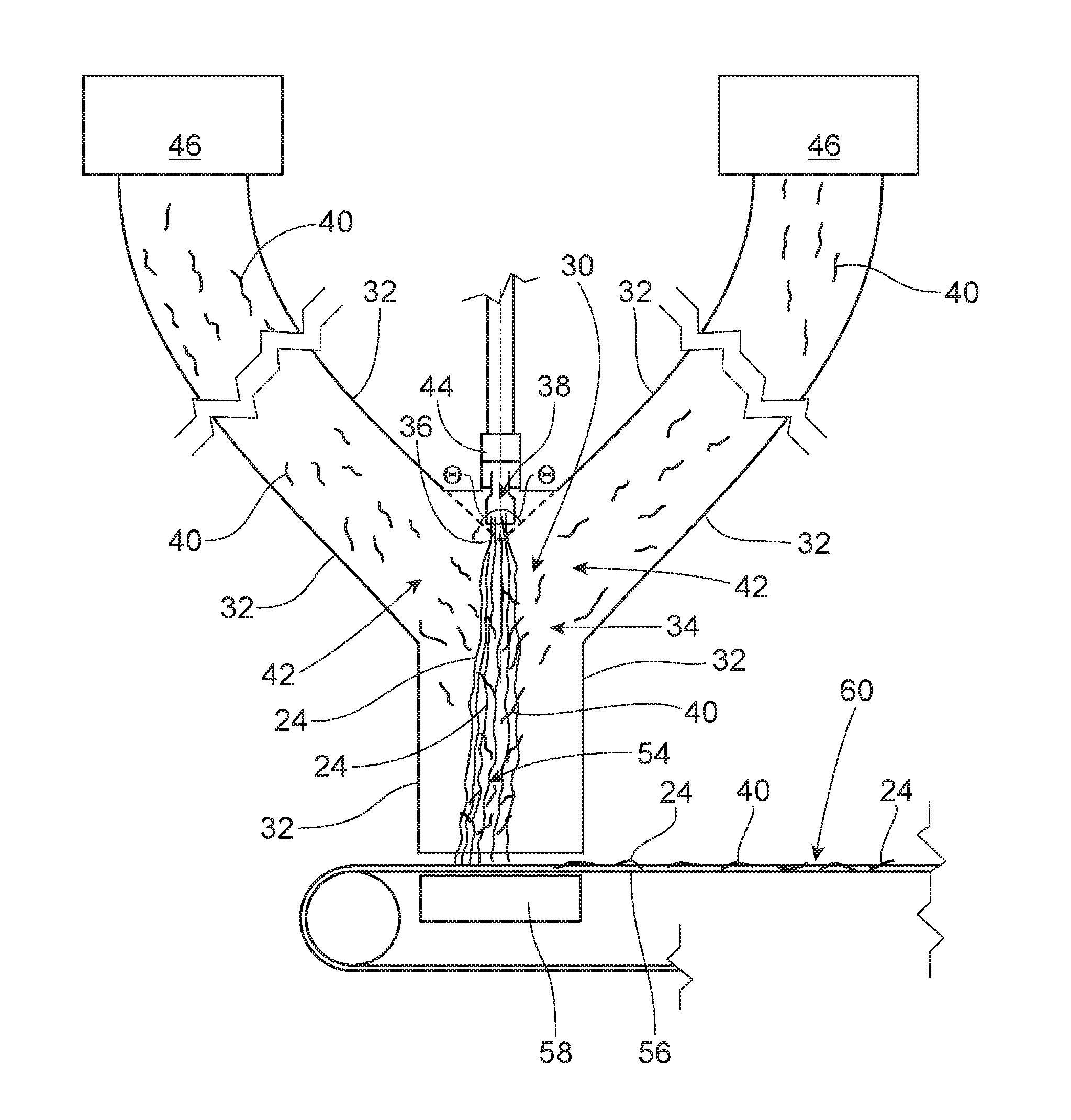
[0194]A 47.5%:27.5%:20.0%:5% blend of Equistar MF650x polypropylene:Equistar 650W polypropylene:Equistar PH835 polypropylene:Polyvel S-1416 wetting agent is dry blended, to form a melt blend. The melt blend is heated to 475° F. through a melt extruder. A 15.5″ wide Biax 12 row spinnerette with 192 nozzles per cross-direction inch, commercially available from Biax Fiberfilm Corporation, is utilized. 40 nozzles per cross-direction inch of the 192 nozzles have a 0.018″ inside diameter while the remaining nozzles are unused for PP delivery Approximately 0.19 grams per hole per minute (ghm) of the melt blend is extruded from the open nozzles to form meltblown filaments from the melt blend. Approximately 420 SCFM of compressed air is heated such that the air exhibits a temperature of 395° F. at the spinnerette. Approximately 500 grams / minute of Koch 4825 semi-treated SSK pulp is defibrillated through a hammermill to form SSK wood pulp fibers (solid additive). Approximately 1600 SCFM of ai...

example 2

[0197]A 20%:27.5%47.5%:5% blend of Lyondell-Basell PH835 polypropylene:Lyondell-Basell Metocene MF650W polypropylene:Exxon-Mobil PP3546 polypropylene:Polyvel S-1416 wetting agent is dry blended, to form a melt blend. The melt blend is heated to 400° F. through a melt extruder. A 15.5 inch wide Biax 12 row spinnerette with 192 nozzles per cross-direction inch, commercially available from Biax Fiberfilm Corporation, is utilized. 40 nozzles per cross-direction inch of the 192 nozzles have a 0.018 inch inside diameter while the remaining nozzles are solid, i.e. there is no opening in the nozzle. Approximately 0.19 grams per hole per minute (ghm) of the melt blend is extruded from the open nozzles to form meltblown filaments from the melt blend. Approximately 415 SCFM of compressed air is heated such that the air exhibits a temperature of 395° F. at the spinnerette. Approximately 475 g / minute of a blend of 70% Golden Isle (from Georgia Pacific) 4825 semi-treated SSK pulp and 30% Eucalypt...


PUM

PropertyMeasurementUnit
angleaaaaaaaaaa
angleaaaaaaaaaa
lengthaaaaaaaaaa

Abstract

Coforming processes for commingling two or more separate materials, for example solid additives, for example fibers and / or particulates, and filaments, and equipment; namely, forming boxes, useful in such coforming processes and more particularly to coforming processes for commingling filaments with one or more fibers, such as pulp fibers, and forming boxes useful therein are provided.

Description

FIELD OF THE INVENTION[0001]The present invention relates to coforming processes for commingling two or more materials, for example solid additives, for example fibers and / or particulates, and filaments, and equipment; namely, forming boxes, useful in such coforming processes and more particularly to coforming processes for commingling filaments with one or more fibers, such as pulp fibers, and forming boxes useful therein.BACKGROUND OF THE INVENTION[0002]Forming boxes have been used in the past to facilitate the commingling (“coforming”) of two or more materials such as filaments and fibers during a fibrous structure making process. However, the known forming boxes were designed to have one material, for example pulp fibers, being injected into another material, for example filaments, in a perpendicular fashion (90° to one another) as shown in Prior Art FIG. 1. The prior art forming box (coform box) 10 shown in FIG. 1 has a first material inlet 12 and a second material inlet 14. Fi...

Claims


Application Information

Patent Timeline
Patent Type & Authority Applications(United States)
IPC IPC(8): D01D5/06
CPCD01D5/06D01D5/00D01D5/0985D01F11/00D04H1/732D04H1/565
Inventor YOUNG, CHRISTOPHER MICHAELWANG, FEIBARNHOLTZ, STEVEN LEEEROGLU, HASANSTEWART, EDWIN ARTHURMCKIBBEN, JOHN FERNEYMELLIN, GUSTAV ANDRE
Owner THE PROCTER & GAMBLE COMPANY
Why Eureka
Try Eureka