
Chip package structure and method for forming chip package

a chip package and chip technology, applied in the field of chip package structure and a chip package forming method, can solve the problems of increasing the manufacture cost of the chip, not being able to meet the requirement of ultra-high density chip package with i/o terminals, and not being able to form the chip package by using bonding wires, etc., to achieve the effect of ultra-high density

Active Publication Date: 2016-12-01
SILERGY SEMICON TECH (HANGZHOU) CO LTD
View PDF6 Cites 1 Cited by
  • Summary
  • Abstract
  • Description
  • Claims
  • Application Information

AI Technical Summary

Benefits of technology

The patent describes a chip package structure and method that increases the area of a package by using a bigger chip and a surrounding encapsulant. The structure also includes a layer that draws out and redistributes input / output terminals on the chip surface. This layer is then connected to a leadframe or printed circuit board through external and electrical connectors. The technical benefits of this invention are increased density of input / output terminals, reduced package cost, and improved package reliability.

Problems solved by technology

Such method of forming the chip package by using bonding wires is not suitable for forming a chip package having input / output (I / O) terminals with a high density, because pins are provided around the chip and pitches between adjacent ones of the pins should be no less than a predetermined value for an encapsulant.
Nevertheless, the method will increase manufacture cost of the chip.
Thus, the CSP package and the flip-chip package still do not satisfy the requirement of the chip package with I / O terminals having ultra-high density.

Method used


Image

  • Chip package structure and method for forming chip package
  • Chip package structure and method for forming chip package
  • Chip package structure and method for forming chip package

Examples


Embodiment Construction

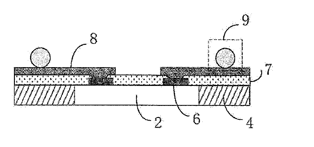
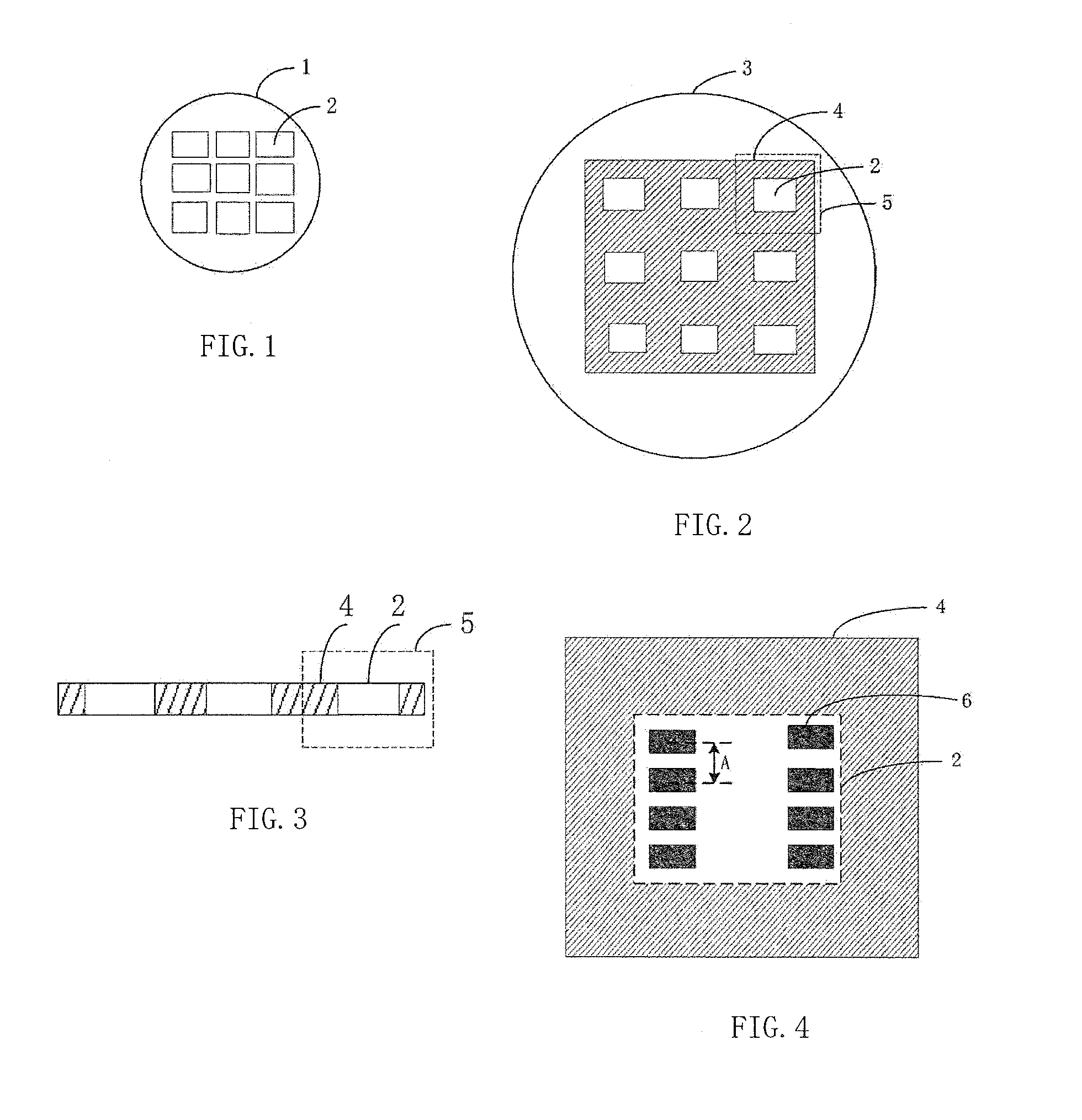
[0034]Exemplary embodiments of the present disclosure will be described in more details below with reference to the accompanying drawings. In the drawings, like reference numerals denote like members. The figures are not drawn to scale, for the sake of clarity. Moreover, some well known parts may not be shown. For simplicity, the package structure having been subject to several relevant process steps may be shown in one figure. Some particular details of the invention will be described, such as an exemplary structure, material, dimension, process step and fabricating method of the device, for a better understanding of the present invention. However, it can be understood by one skilled person in the art that these details are not always essential for but can be varied in a specific implementation of the disclosure.

[0035]According to an embodiment of the present disclosure, there is provided a method for forming a chip package, including the following steps.

[0036]In step 1, chips are ...


PUM


Abstract

The present disclosure relates to a chip package structure and a method for forming a chip package. A package unit is formed from the chip and an encapsulant surrounding the chip to have an increased area. A redistribution layer is formed on the package unit to draw out to and redistribute input / output terminals on a surface of the chip. The redistribution layer is then electrically coupled to a leadframe or a printed circuit board by external and electrical connectors. The method and the package structure are suitable for providing a chip package having input / output terminals with high density, reducing package cost, and improving package reliability.

Description

CLAIM OF PRIORITY[0001]This application claims priority to Chinese Application No. 201510283826.8, filed on May 28, 2015, which is hereby incorporated by reference.BACKGROUND OF THE DISCLOSUREField of the Disclosure[0002]The present disclosure generally relates to the field of a chip package, and more particularly, to a chip package structure and a method for forming a chip package.Description of the Related Art[0003]A conventional method for forming a chip package includes the steps of singulating chips by cutting a wafer, attaching each chip to a leadframe, electrically coupling input / output pads on the chip to the leadframe by metal wires, and encapsulating the chip to form a chip package. Such method of forming the chip package by using bonding wires is not suitable for forming a chip package having input / output (I / O) terminals with a high density, because pins are provided around the chip and pitches between adjacent ones of the pins should be no less than a predetermined value...

Claims


Application Information

Patent Timeline
Patent Type & Authority Applications(United States)
IPC IPC(8): H01L23/495H01L23/31H01L23/00H01L21/48H01L21/56H01L21/78
CPCH01L23/49575H01L21/568H01L21/78H01L24/09H01L2224/0231H01L23/49541H01L23/3114H01L2224/12105H01L21/4853H01L24/19H01L24/96H01L2924/18162H01L23/49816H01L23/5389H01L23/3128H01L24/20H01L2924/00014H01L2224/05553H01L2224/06135H01L24/05H01L24/06H01L2224/05599
Inventor YE, JIAMING
Owner SILERGY SEMICON TECH (HANGZHOU) CO LTD
Learn More