
Waste heat utilization arrangement of an internal combustion engine

a technology of waste heat and internal combustion engine, which is applied in the direction of machines/engines, refrigeration components, lighting and heating apparatus, etc., can solve the problems of loss of pressure at the filter element, and achieve the effects of convenient disposal, cost saving, and convenient disposal

Inactive Publication Date: 2016-11-24
ROBERT BOSCH GMBH
View PDF5 Cites 0 Cited by
  • Summary
  • Abstract
  • Description
  • Claims
  • Application Information

AI Technical Summary

Benefits of technology

The waste heat utilization arrangement for an internal combustion engine described in this patent has the advantage that the filter element is placed in a separate line, outside of the main circuit. This prevents any decrease in pressure caused by the filter element. This makes the arrangement more efficient in utilizing waste heat.

Problems solved by technology

As a result, a loss of pressure at the filter element occurs only at the beginning of the operation of the waste heat utilization arrangement.

Method used


Image

  • Waste heat utilization arrangement of an internal combustion engine
  • Waste heat utilization arrangement of an internal combustion engine
  • Waste heat utilization arrangement of an internal combustion engine

Examples


Embodiment Construction

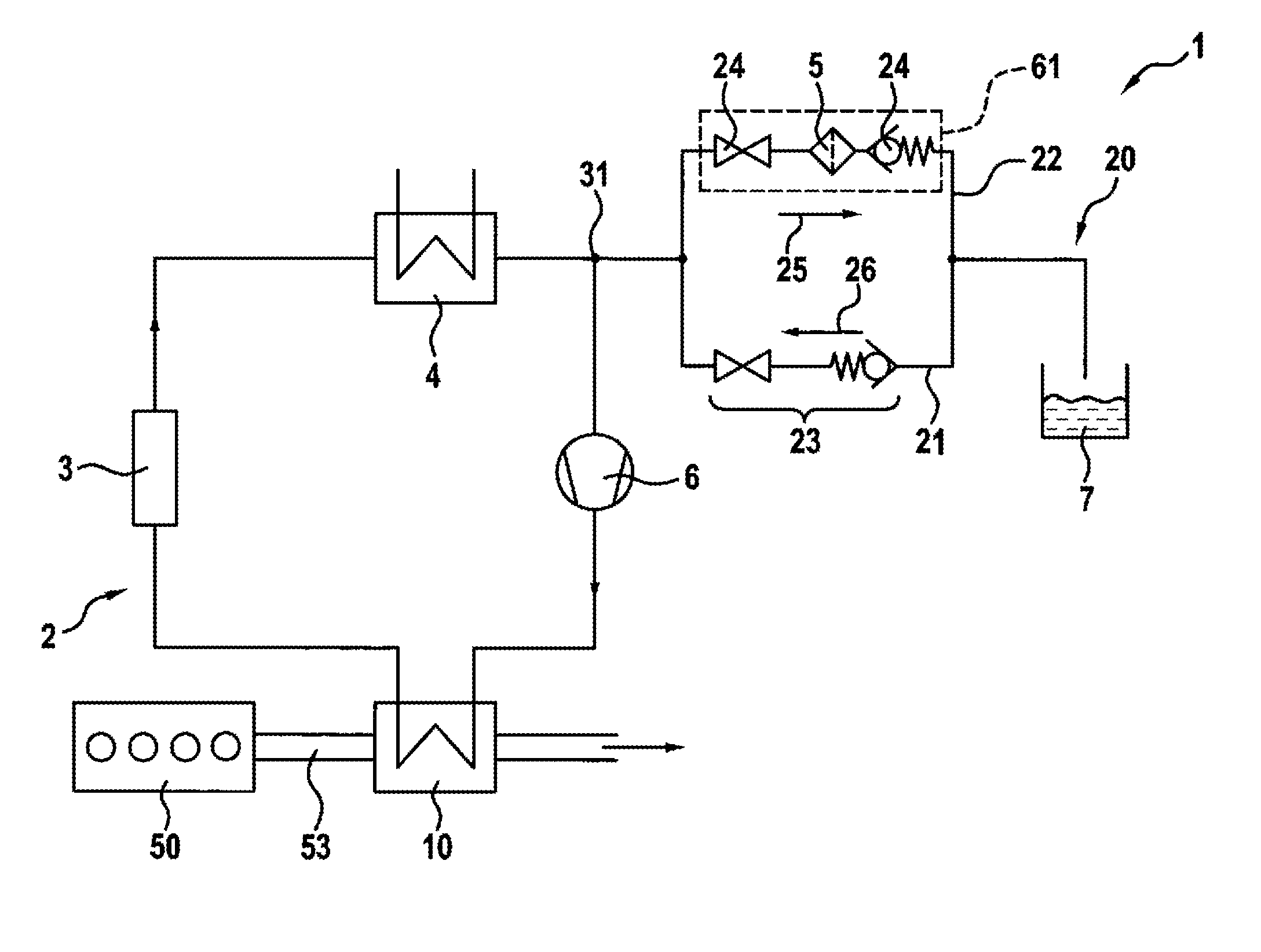
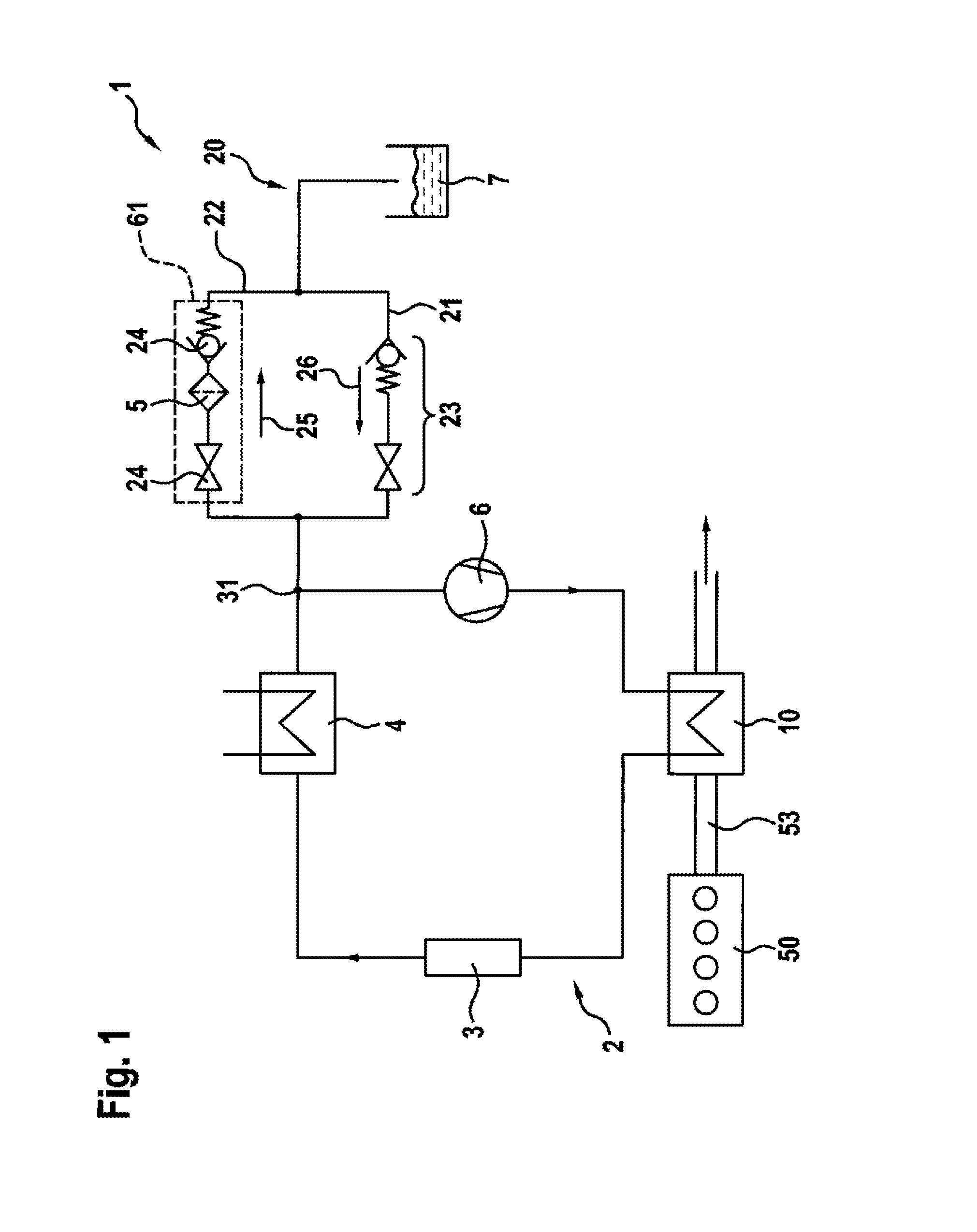
[0027]FIG. 1 shows schematically a waste heat utilization arrangement 1 of an internal combustion engine 50 comprising a main circuit 2 which carries a working medium and a secondary line 20 which can be connected to the main circuit.

[0028]Fresh air, which can also contain recirculated exhaust gas of the internal combustion engine 50, is supplied to the internal combustion engine 50 on the input side. On the output side, the internal combustion engine 50 has an exhaust duct 53 through which the exhaust gas is discharged from said internal combustion engine 50.

[0029]The main circuit 210 comprises a feed pump 6, an evaporator 10, an expansion machine 3 and a condenser 4 in the direction of flow of the working medium. The evaporator 10 is simultaneously disposed in the exhaust duct 53; thus enabling the thermal energy of the exhaust gas to be transferred out of the exhaust duct 53 into the main circuit 2.

[0030]The waste heat utilization arrangement 1 further comprises a secondary line ...


PUM


Abstract

Waste heat utilization arrangement (1) of an internal combustion engine (50), comprising a main circuit (2) which carries a working medium, wherein a feed pump (6), an evaporator (10), an expansion machine (3) and a condenser (4) are disposed in the main circuit (2) in the direction of flow of the working medium. The evaporator (10) is also disposed in an exhaust duct (53) of the internal combustion engine (50). The waste heat utilization arrangement (1) comprises a secondary line (20) which can be connected to the main circuit (2). A filter element (5) is disposed in the secondary line (2b, 20, 30).

Description

BACKGROUND OF THE INVENTION[0001]The invention relates to a waste heat utilization arrangement of an internal combustion engine.[0002]Waste heat utilization arrangements of internal combustion engines are known from the prior art, such as, for example, from the published Japanese patent application JP 11-093689 A. The known waste heat utilization arrangement of an internal combustion engine comprises a main circuit which carries a working medium, a feed pump, an evaporator, an expansion machine and a condenser being disposed in the main circuit in the direction of flow of the working medium. The evaporator is also disposed in an exhaust duct of the internal combustion engine; thus enabling the thermal energy of the exhaust to evaporate the working medium in the evaporator.[0003]The known waste heat utilization arrangement further comprises a filter element in the main circuit so that the working medium is continually filtered. The filter element therefore has a continuous pressure l...

Claims


Application Information

Patent Timeline
Patent Type & Authority Applications(United States)
IPC IPC(8): F01N5/02F02M26/14F25B5/02F25B43/00F25B45/00F25B41/04F01N13/08B60H1/20
CPCF01N5/02F01N13/08F02M26/14B60H1/20F25B5/02F25B45/00F25B41/043F25B41/04F25B43/003F01K23/065F01K23/10F02M26/22Y02T10/12
Inventor KOCH, ANSELMMAIER, EBERHARD
Owner ROBERT BOSCH GMBH
Learn More