
Apparatus for bending glass panels

A glass plate, bending technology, applied in glass manufacturing equipment, glass transportation equipment, glass forming, etc., can solve unused problems

Inactive Publication Date: 2008-03-05
TAMGLASS LTD OY
View PDF9 Cites 0 Cited by
  • Summary
  • Abstract
  • Description
  • Claims
  • Application Information

AI Technical Summary

Problems solved by technology

However, these known devices do not use a mold truck with a lightweight construction and an open bottom that can recover heat from the annealed glass

Method used


Image

  • Apparatus for bending glass panels
  • Apparatus for bending glass panels
  • Apparatus for bending glass panels

Examples


Embodiment Construction

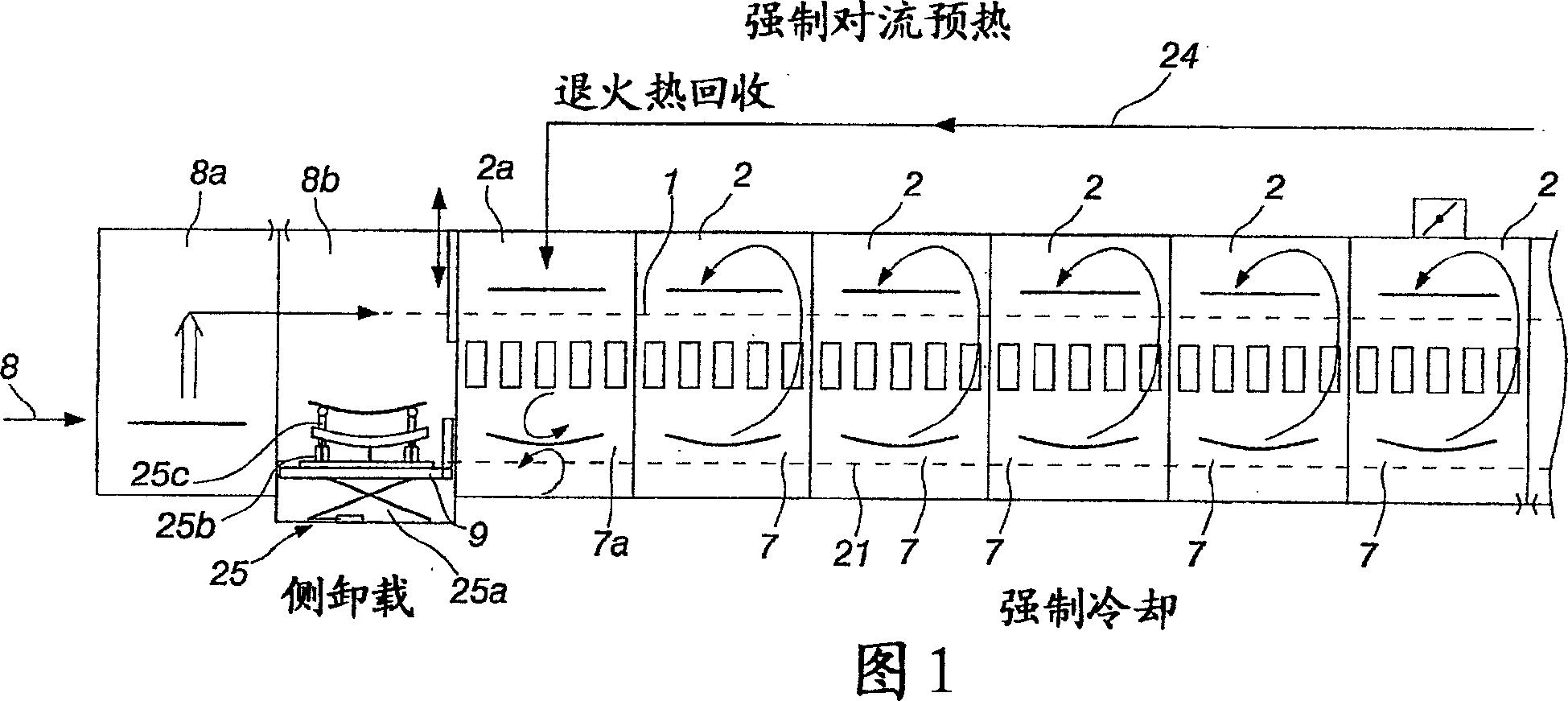
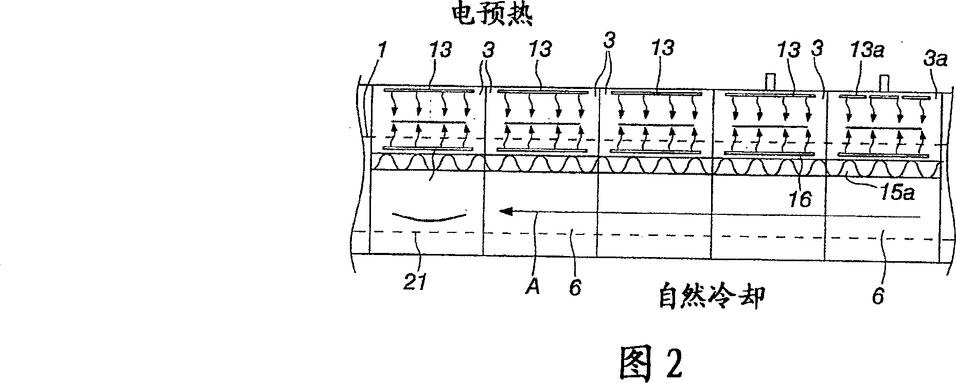
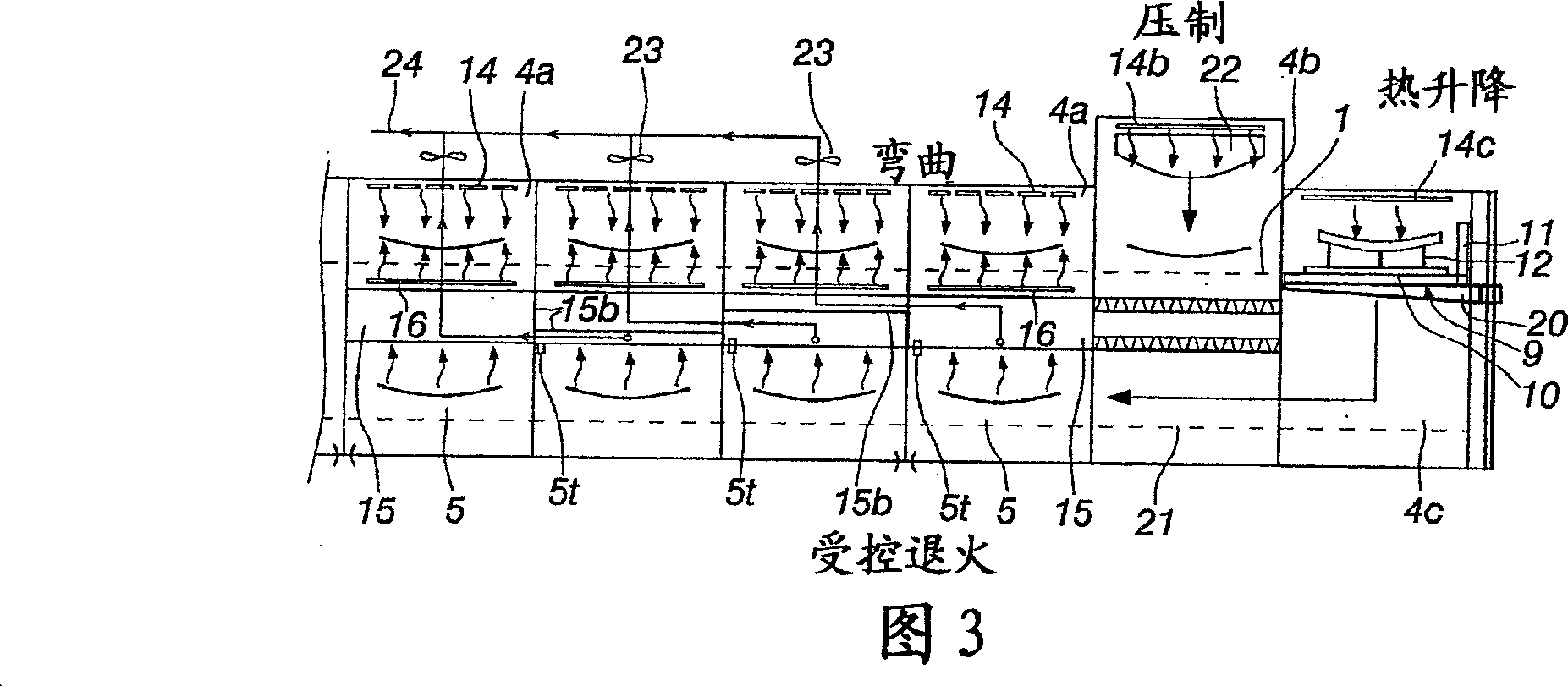
[0023] The equipment shown in Figures 1-3 includes an upper mold carriage guide rail 1 with a continuous mold carriage 9, the front wall or rear wall 11 of the mold carriage connects the continuous preheating chambers 2, 3 and several continuous bending chambers 4a, 4b are spaced apart from each other. The mold carrier is suitable for intermittent delivery to the last bending chamber 4b, and a liftable male mold 22 is arranged on the top plate of the bending chamber. The lower mold carriage guide rail 21 carries the continuous mold carriage 9 located below the mold carriage of the upper guide rail 1 . The mold truck 9 of the lower mold truck rail 21 has a rear or front wall 11 separating successive cooling chambers 5, 6 and 7 from each other. The mold carriage 9 of the lower guide rail 21 is suitable for intermittent conveyance along the direction opposite to the conveying direction of the mold carriage located on the upper mold carriage guide rail.

[0024] Each mold truck ...


PUM


Abstract

The invention relates to an apparatus for bending glass panels. An upper tier of successive mould carriages (9) defines a number of heating compartments, the last one constituting an actual bending compartment (4b). A lower tier of successive mould carriages (9) defines a number of cooling compartments (5, 6, 7), which are located underneath the heating compartments. The mould carriages are provided with an open-structured or otherwise highly heat transmissive bottom (10). The mould supporting carriage (9) is provided with mould bearer elements (26) and the final bending compartment (4b) has its lower section provided with ascendable and descendable brace elements (27), which provide bracing for the bearer elements (26) during a pressing operation performed by means of a male mould (22). In connection with the brace elements (27) are further provided lifting and lowering mechanisms for the brace elements (27).

Description

technical field [0001] The invention relates to an apparatus for bending glass sheets, said apparatus comprising: [0002] - an upper carriage rail with a continuous (successive) carriage (mold carriage) whose front or rear wall separates a continuous heating chamber and several successive bending chambers from each other, the carriage The mold car is suitable for intermittent transmission to the bending chamber, and the top plate (top wall) of the bending chamber is provided with a liftable male mold; [0003] - a lower cart rail with a continuous cart, the rear or front wall of which separates successive cooling chambers from each other, adapted to lie along and on said upper cart rail Intermittent transmission in the opposite direction of the transmission direction of the model transport vehicle; [0004] - a plurality (s) of bending dies supported by said carriage; [0005] - a preheating chamber located at the upstream end of the upper carriage rails, in which preheati...

Claims


Application Information

Patent Timeline
Patent Type & Authority Patents(China)
IPC IPC(8): C03B23/03C03B35/20C03B23/025C03B25/08C03B29/08
CPCC03B29/08C03B25/08C03B23/0258C03B23/03C03B35/202
Inventor E·于利-瓦库里H·科伊维斯托
Owner TAMGLASS LTD OY
Learn More