Electron beam melting and laser milling composite 3D printing apparatus

a 3d printing and laser milling technology, applied in the direction of soldering apparatus, manufacturing tools, welding devices, etc., can solve the problems of stress deformation large shape error of formed components, etc., to improve milling machining accuracy, large machining error, and wide application space

Inactive Publication Date: 2016-11-10
YUANMENG PRECISION TECH SHENZHEN INST
View PDF11 Cites 13 Cited by
  • Summary
  • Abstract
  • Description
  • Claims
  • Application Information

AI Technical Summary

Benefits of technology

[0020]Compared with the prior art, in the electron beam melting and laser milling composite 3D printing apparatus provided by the present application, the electron beam emitted by the electron beam emitting structure is used to melt layer by layer the metal powder layer, the laser beam emitted by the laser milling head is used to mill the single-layer or multi-layer approximate body, and the above steps are repeated until the machining of the component is finished. The 3D printing apparatus integrates a traditional removal accurate machining taking laser milling as a main method with an incremental laminating manufacturing process taking electron beam melting 3D printing as a main method together. Therefore, not only are the defects of the traditional 3D printing technology in aspects such as size and shape accuracy overcome, but also the restrictions of cutting machining to the complexity of components or the like are overcome too. In this way, the machined components do not need to be machined secondarily, and the problems of difficult clamping, large machining error, deformation of components occurring during machining, and difficult machining are avoided, the 3D printing technology achieves wider application space, and a new method and technical means are provided to the production and manufacturing of core and precision components in the aerospace industry. Furthermore, using the laser beam to mill the single-layer or multi-layer approximate body belongs to a non-contact milling machining, and the defects existing in the directly contact machining in which a traditional tool directly contacts with a single-layer or multi-layer approximate body are avoided, so that the milling machining accuracy is improved greatly.

Problems solved by technology

However, the formed component has a large shape error and a poor surface finish; therefore, the formed component needs to be machined secondarily using a traditional machining method, only by this can the component obtain a shape and a surface accuracy meeting the requirements of aviation manufacturing industry.
Besides, most components used in the aerospace industry, such as engine nozzles, blades, cellular combustion chambers or the like, are complicated thin-wall structures or truss core structures, or have a relatively large shape, or are in a shape of a free-form surface or the like; when a component produced by the metal melting 3D printing technology is further put onto a lathe for a secondary machining, the following problems may exist:1) clamping is difficult, or after clamping, the machining error is large because it is impossible to position reference points of the component accurately due to a transformation of coordinates;2) for a component having a thin-wall structure, during machining, stress deformation may occur in the component because there is no surface supporting the component;3) some components may be difficult to machine because their inner structures are complicated and a tool is unable to enter the inside of such a component.
Due to the existence of the above problems, though the metal melting 3D printing technology has been applied into the producing and manufacturing of aircraft parts now, it has a narrow application range; it is only used for machining some components having low requirements for accuracies and strengths, or some components having simpler structures and being easy to be machined secondarily, and is far from being widely used.

Method used


Image

  • Electron beam melting and laser milling composite 3D printing apparatus
  • Electron beam melting and laser milling composite 3D printing apparatus
  • Electron beam melting and laser milling composite 3D printing apparatus

Examples


Embodiment Construction

[0023]In order to make the objective, the technical solution and the advantages of the present application more clear, the present application is further explained in detail with reference to the accompanying drawings and embodiments. It should be understood that, the specific embodiments described herein are only used for explaining the present application, and are not a limitation to the present application.

[0024]Embodiments of the present application are described in detail with reference to the specific embodiments in the following.

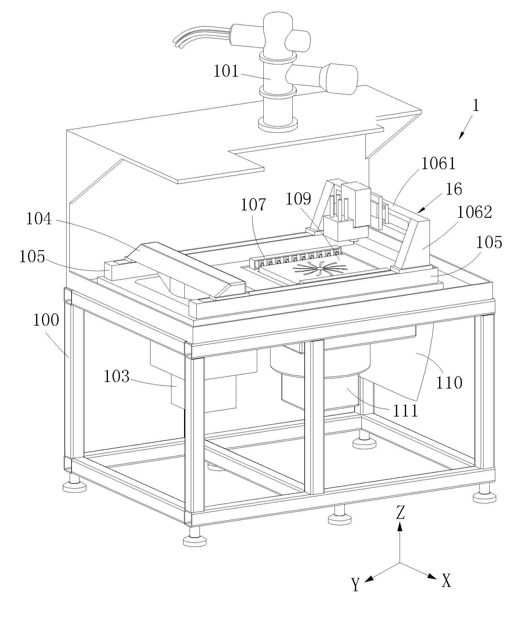
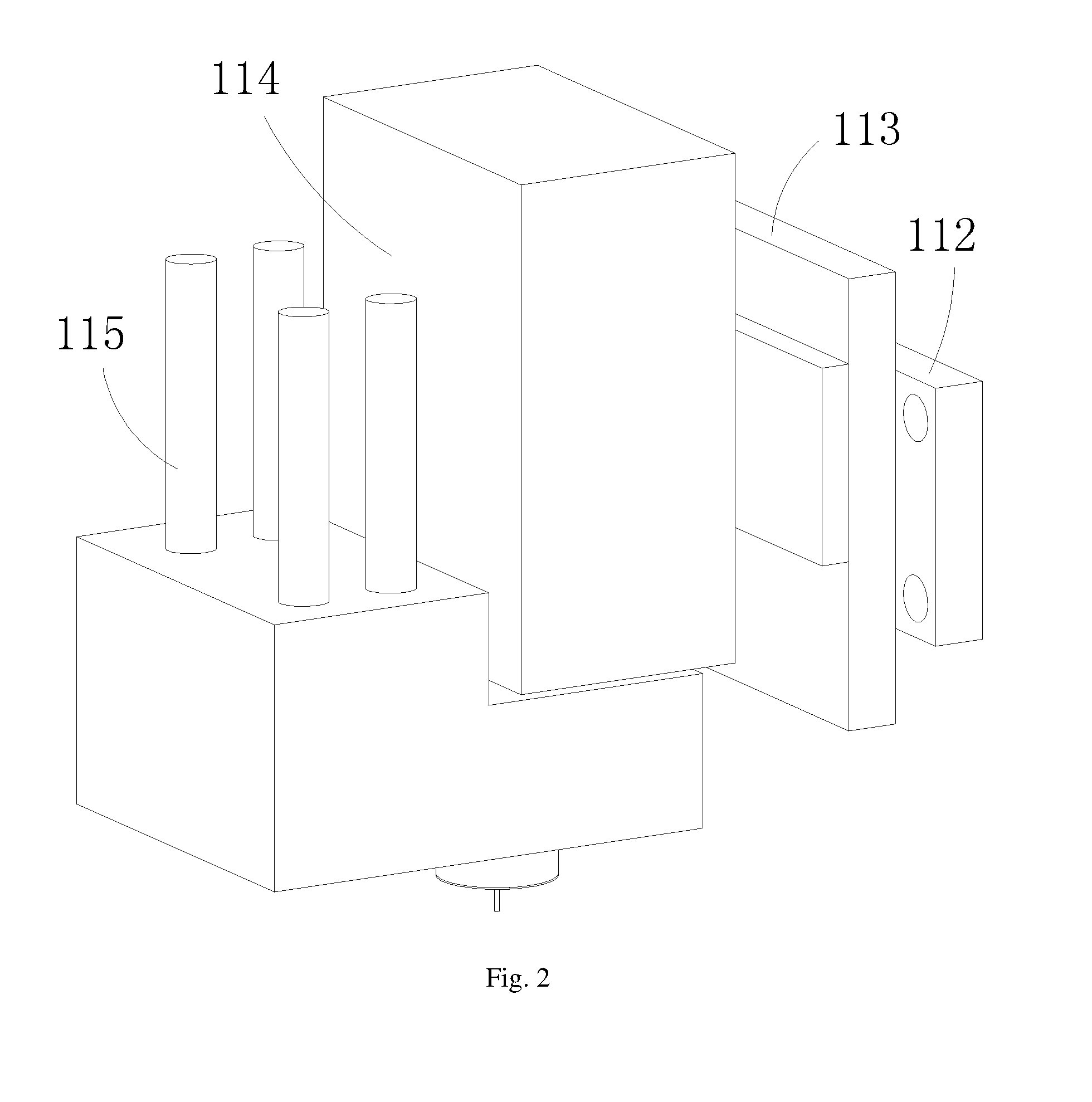
[0025]FIGS. 1-2 show a preferred embodiment provided by the present application.

[0026]A 3D printing apparatus 1 provided by the present application combines laser milling machining with electron beam melting, and may be used to form various components, such as the components required in the aviation manufacturing industry, or the like.

[0027]The electron beam melting and laser milling composite 3D printing apparatus 1 comprises a base 100, a powder spr...


PUM

PropertyMeasurementUnit
thicknessaaaaaaaaaa
magnetic fieldaaaaaaaaaa
strengthaaaaaaaaaa

Abstract

The present application relates to the technical field of 3D printing apparatus, and discloses an electron beam melting and laser milling composite 3D printing apparatus which comprises a base, in which a powder spreading structure configured for spreading metal powders onto the machining platform is arranged on the base, an electron beam emitting structure and a laser milling head are arranged above the machining platform, the electron beam emitting structure is configured for emitting an electron beam to melt the metal powder layer to form a single-layer or multi-layer approximate body, and the laser milling head is configured for emitting a laser beam to mill the single-layer or multi-layer approximate body.

Description

TECHNICAL FIELD[0001]The present application relates to the technical field of 3D (three-dimensional) printing apparatuses, and more particularly, relates to an electron beam melting and laser milling composite 3D printing apparatus.BACKGROUND[0002]Metal melting 3D printing technology (Selective Laser Melting, SLM) is a kind of technology using high-brightness laser to directly melt metal power materials, and directly forming a component with any complicated structure, which has properties similar to a casting, via a 3D model, without adhesives.[0003]By means of the metal melting 3D printing technology, a component having a strength level reaching that of a casting can be formed. However, the formed component has a large shape error and a poor surface finish; therefore, the formed component needs to be machined secondarily using a traditional machining method, only by this can the component obtain a shape and a surface accuracy meeting the requirements of aviation manufacturing indu...

Claims


Application Information

Patent Timeline
Patent Type & Authority Applications(United States)
IPC IPC(8): B23K28/02B33Y40/00B23K15/00B23K26/12B23K26/346B23K37/02B23K26/70B33Y30/00B23K26/362
CPCB23K28/02B33Y30/00B33Y40/00B23K15/0086B23K26/127B23K26/346B23K37/0235B23K26/703B23K26/1224B23K26/362B23P23/04B23K15/002B23K15/06B23K26/0869B22F2999/00B23K26/342Y02P10/25B22F12/49B22F12/30B22F12/67B22F10/28B22F10/73B22F12/90B22F12/20B22F12/224B22F2003/247B22F2202/05B22F2202/06B22F2003/245B22F3/005B22F2201/10B22F2201/20
Inventor XU, YILI, JUNQINIE, YAN
Owner YUANMENG PRECISION TECH SHENZHEN INST
Why Eureka
Try Eureka