Organic light emitting diode display
a light-emitting diode and organic technology, applied in the direction of diodes, organic semiconductor devices, semiconductor devices, etc., can solve the problems of destructive interference between external light reflected by the first metal layer and external light reflected by the second metal layer, so as to increase light efficiency, reduce the thickness of the display, and not deteriorate contrast and visibility.
- Summary
- Abstract
- Description
- Claims
- Application Information
AI Technical Summary
Benefits of technology
Problems solved by technology
Method used
Image
Examples
first embodiment
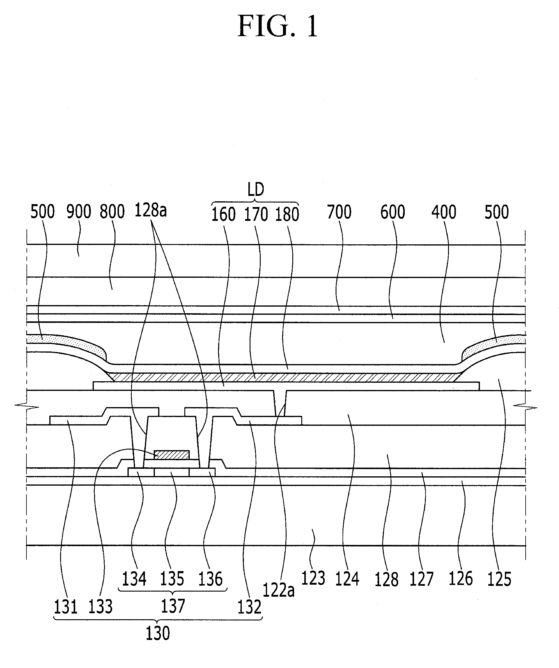
[0041]Hereinafter, an organic light emitting diode display will be described with reference to FIGS. 1 and 2.
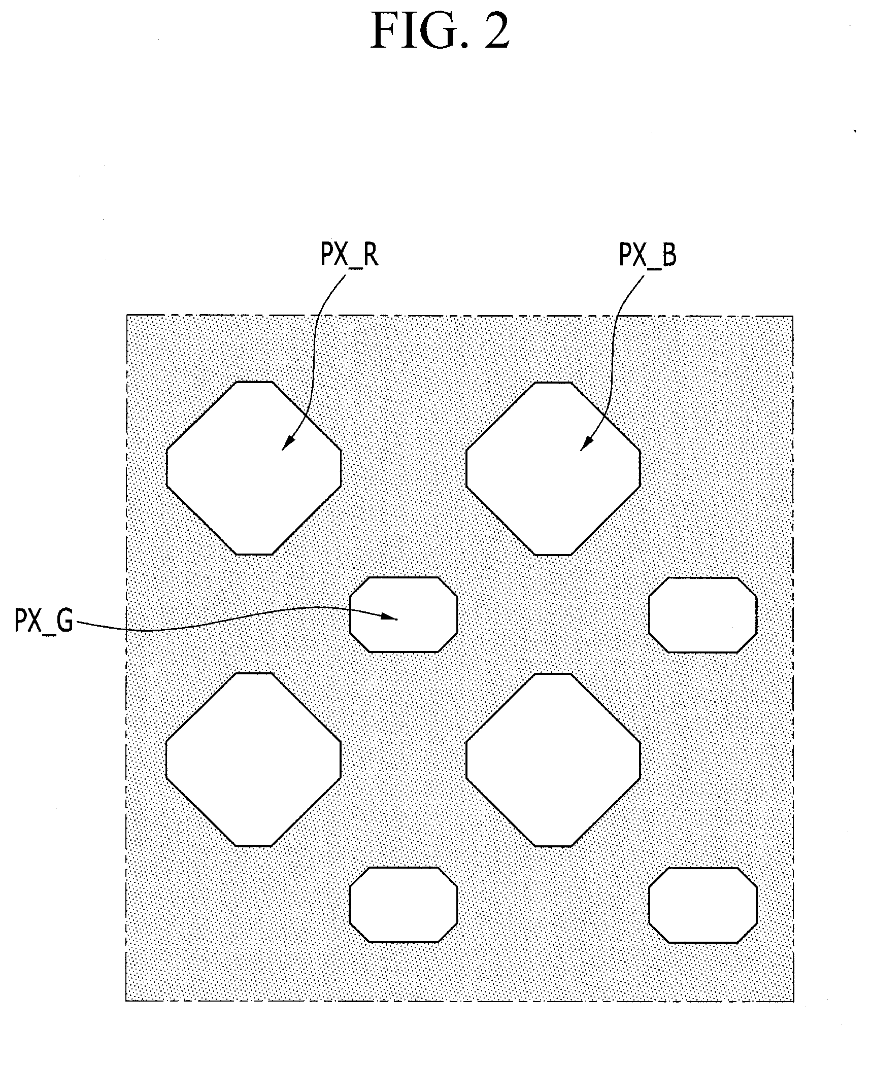
[0042]FIG. 1 is a schematic cross-sectional view of the organic light emitting diode display. FIG. 2 is a plan view of the organic light emitting diode display in which a light blocking layer is disposed.
[0043]Referring to FIG. 1, the organic light emitting diode display includes a substrate 123, a thin film transistor 130, a pixel defining layer 125, a first electrode 160, an organic light emitting layer 170, a second electrode 180, and a light blocking layer 500.
[0044]The substrate 123 may be formed as an insulating substrate made of glass, quartz, ceramic, plastic, or the like. However, the present invention is not limited thereto, and in other embodiments, the substrate 123 may be made of an insulating material having flexibility such as one or more of polyimide (PI), polyetherimide (PEI), polyethylene terephthalate (PET), polycarbonate (PC), polymethylmethacrylate (PMMA...
second embodiment
[0072]Hereinafter, an organic light emitting diode display will be described with reference to FIG. 3. Detailed descriptions of the same or similar components to those of FIG. 1 may not be repeated.
[0073]FIG. 3 is a schematic cross-sectional view of the organic light emitting diode display. Referring to the organic light emitting diode display of FIG. 3, a color filter layer 530 contacting the second electrode 180 may be disposed at a position corresponding to the pixel area.
[0074]In the embodiment of FIG. 1, the light blocking layer 500 is disposed on the second electrode 180, exposing the second electrode 180 at positions corresponding to the pixel area.
[0075]In FIG. 3, the color filter layer 530 is disposed in the exposure region of the light blocking layer 500. The color filter layer 530 contacts the second electrode 180. In further detail, the color filter layer 530 contacts the second electrode 180 while filling the exposure region of the light blocking layer 500.
[0076]The co...
third embodiment
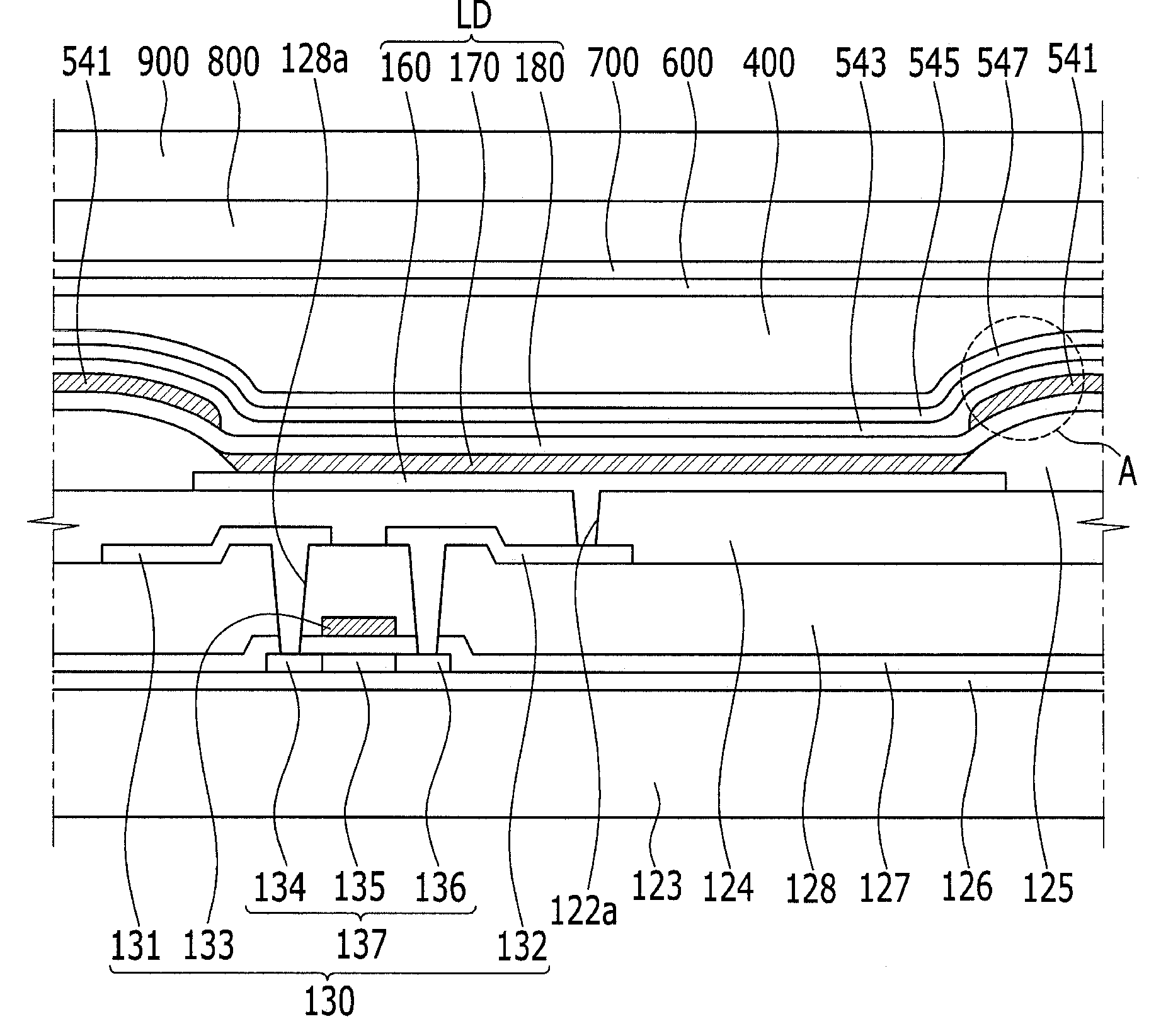
[0082]Hereinafter, an organic light emitting diode display will be described with reference to FIG. 4 in addition to FIGS. 1 and 3 described above. Detailed descriptions of the same or similar components to those of the above-mentioned displays may not be repeated.
[0083]FIG. 4 is a schematic cross-sectional view of the organic light emitting diode display. Referring to the organic light emitting diode display of FIG. 4, an encapsulation layer 400 is disposed on a second electrode 180 and a light blocking layer 500, unlike the organic light emitting diode display of FIG. 3. In FIG. 4, a color filter layer contacting the second electrode 180 is not disposed on the second electrode 180 at a position corresponding to a pixel area. In other respects, the organic light emitting diode display of FIG. 4 has substantially the same configuration from the substrate 123 to the encapsulation layer 400 of the organic light emitting diode display of FIGS. 1 and 3.
[0084]In the organic light emitti...
PUM
 Abstract
Description
Claims
Application Information
 - R&D
- Intellectual Property
- Life Sciences
- Materials
- Tech Scout
- Unparalleled Data Quality
- Higher Quality Content
- 60% Fewer Hallucinations
Browse by: Latest US Patents, China's latest patents, Technical Efficacy Thesaurus, Application Domain, Technology Topic, Popular Technical Reports.
© 2025 PatSnap. All rights reserved.Legal|Privacy policy|Modern Slavery Act Transparency Statement|Sitemap|About US| Contact US: help@patsnap.com


