Magnetism measuring device, manufacturing method of magnetism measuring device, gas cell, and manufacturing method of gas cell
a technology of gas cell and measuring device, which is applied in the direction of single device manufacturing, magnetic measurement, instruments, etc., can solve the problems of low chemical resistance of low-melting-point glass, high reactivity of metal, and reduced manufacturing yield of gas cell and magnetism measuring device, etc., and achieve the effect of stable manufacturing
- Summary
- Abstract
- Description
- Claims
- Application Information
AI Technical Summary
Benefits of technology
Problems solved by technology
Method used
Image

Examples
first embodiment
Configuration of Magnetism Measuring Device
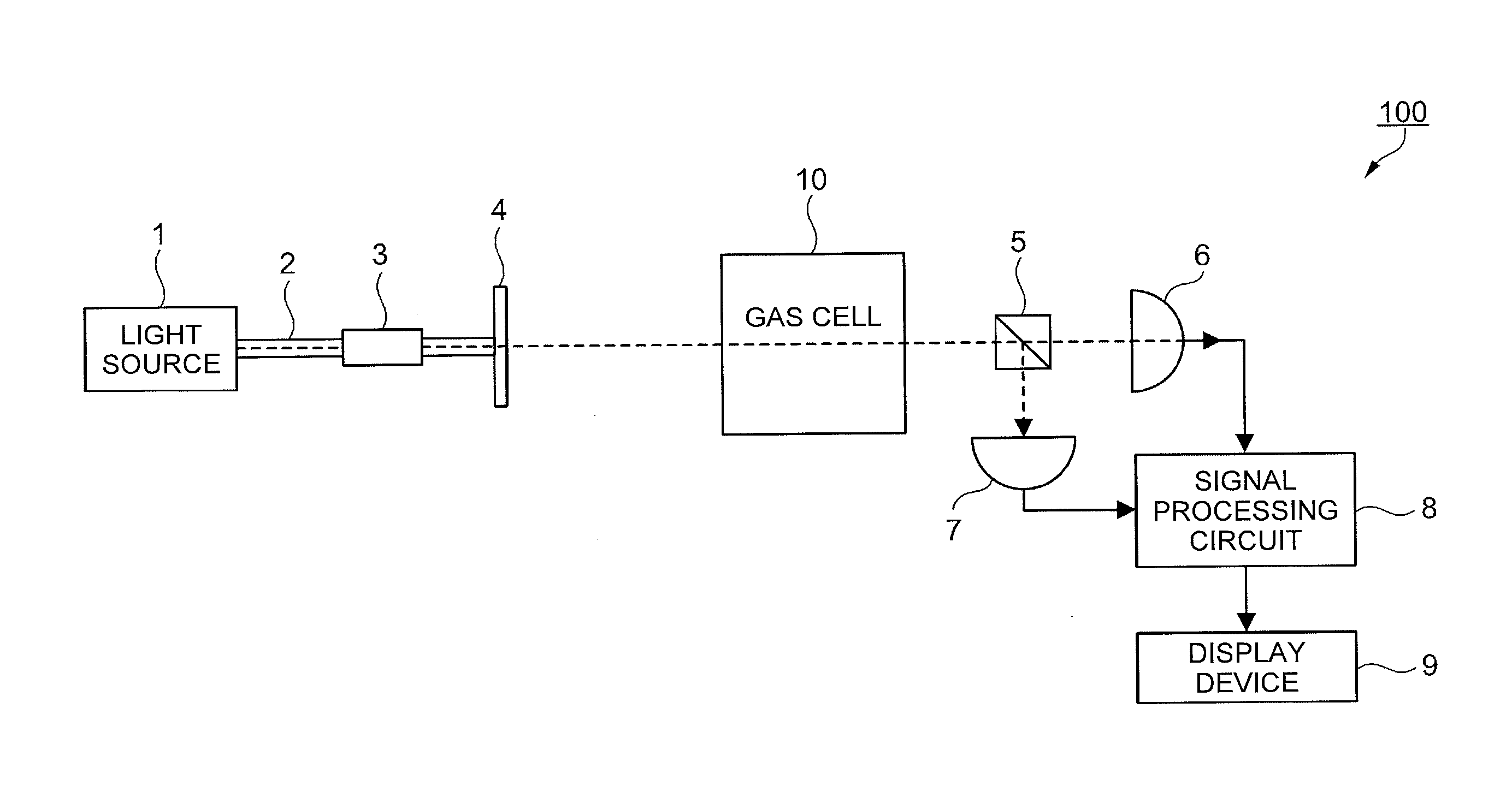
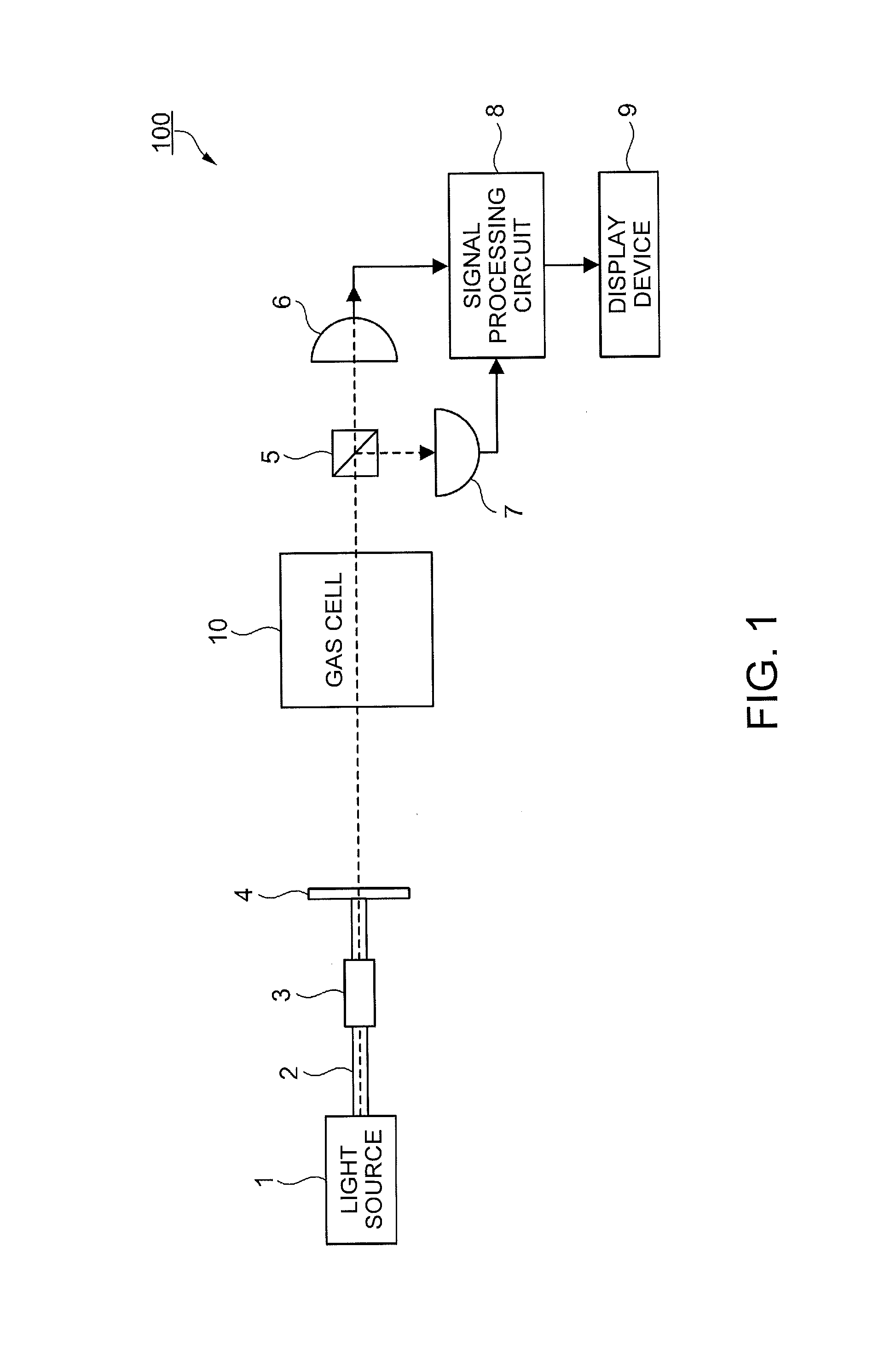
[0051]The configuration of a magnetism measuring device according to a first embodiment will be described with reference to FIG. 1. FIG. 1 is a block diagram illustrating the configuration of the magnetism measuring device according to this embodiment. A magnetism measuring device 100 according to the first embodiment is a magnetism measuring device which uses nonlinear magneto-optical rotation (NMOR). The magnetism measuring device 100 is used in, for example, a living body state measuring device (magnetocardiography, magnetoencephalography, or the like) which measures a weak magnetic field generated from a living body such as a magnetic field from the heart (cardiac magnetism) or a magnetic field from the brain (cerebral magnetism). The magnetism measuring device 100 may also be used in a metal detector or the like.
[0052]As illustrated in FIG. 1, the magnetism measuring device 100 includes a light source 1, an optical fiber 2, a connector...
second embodiment
[0108]In a second embodiment, the configuration of a gas cell is the same as that in the first embodiment, and a manufacturing method of the gas cell is partially different from that in the first embodiment. More specifically, the second embodiment is different from the first embodiment in that a partition plate is used in a cooling process during the manufacturing of the gas cell. The difference in the cooling process from the first embodiment is described herein.
Manufacturing Method of Gas Cell
[0109]FIG. 8 is a view illustrating a heating process and the cooling process in the manufacturing method of the gas cell according to the second embodiment. As illustrated in FIG. 8, the heating process and the cooling process according to the second embodiment are different from those of the first embodiment in that a partition plate 206 which partitions the interior 202 of the oven 200 into a first portion 202a on the inner side (+X direction side in FIG. 8) and a second portion 202b on t...
third embodiment
[0115]In a third embodiment, the configuration of a gas cell is partially different from those of the above-described embodiments, and accordingly a forming process in a manufacturing method of the gas cell is different therefrom. The difference in the configuration of the gas cell and the forming process from the above-described embodiments is described herein. FIGS. 10A to 10C are views illustrating the forming process according to the third embodiment.
Configuration of Gas Cell
[0116]FIG. 10C illustrates a gas cell 10A when the forming process according to the third embodiment is ended. As illustrated in FIG. 10C, the gas cell 10A according to the third embodiment is constituted by a cell portion 12A as a closed container, and the lid portion 19 (see FIG. 2A) which is the same as that in the above-described embodiments. The cell portion 12A includes a concave container body 12a, and an upper lid 12b positioned on the upper side of the container body 12a. The container body 12a incl...
PUM
 Abstract
Description
Claims
Application Information
 - R&D
- Intellectual Property
- Life Sciences
- Materials
- Tech Scout
- Unparalleled Data Quality
- Higher Quality Content
- 60% Fewer Hallucinations
Browse by: Latest US Patents, China's latest patents, Technical Efficacy Thesaurus, Application Domain, Technology Topic, Popular Technical Reports.
© 2025 PatSnap. All rights reserved.Legal|Privacy policy|Modern Slavery Act Transparency Statement|Sitemap|About US| Contact US: help@patsnap.com