
Method and apparatus for estimating uneven tire wear

a tire wear and tire technology, applied in vehicle tyre testing, instrumentation, processing detected response signals, etc., can solve the problems of differences in the amount of wear between the central part and the shoulder parts of the tire tread, and tire wear in the tread surface, so as to improve the accuracy of estimating uneven wear in the tire shoulder, reduce the number of sensors, and reduce the effect of nois

Inactive Publication Date: 2016-09-29
BRIDGESTONE CORP
View PDF4 Cites 6 Cited by
  • Summary
  • Abstract
  • Description
  • Claims
  • Application Information

AI Technical Summary

Benefits of technology

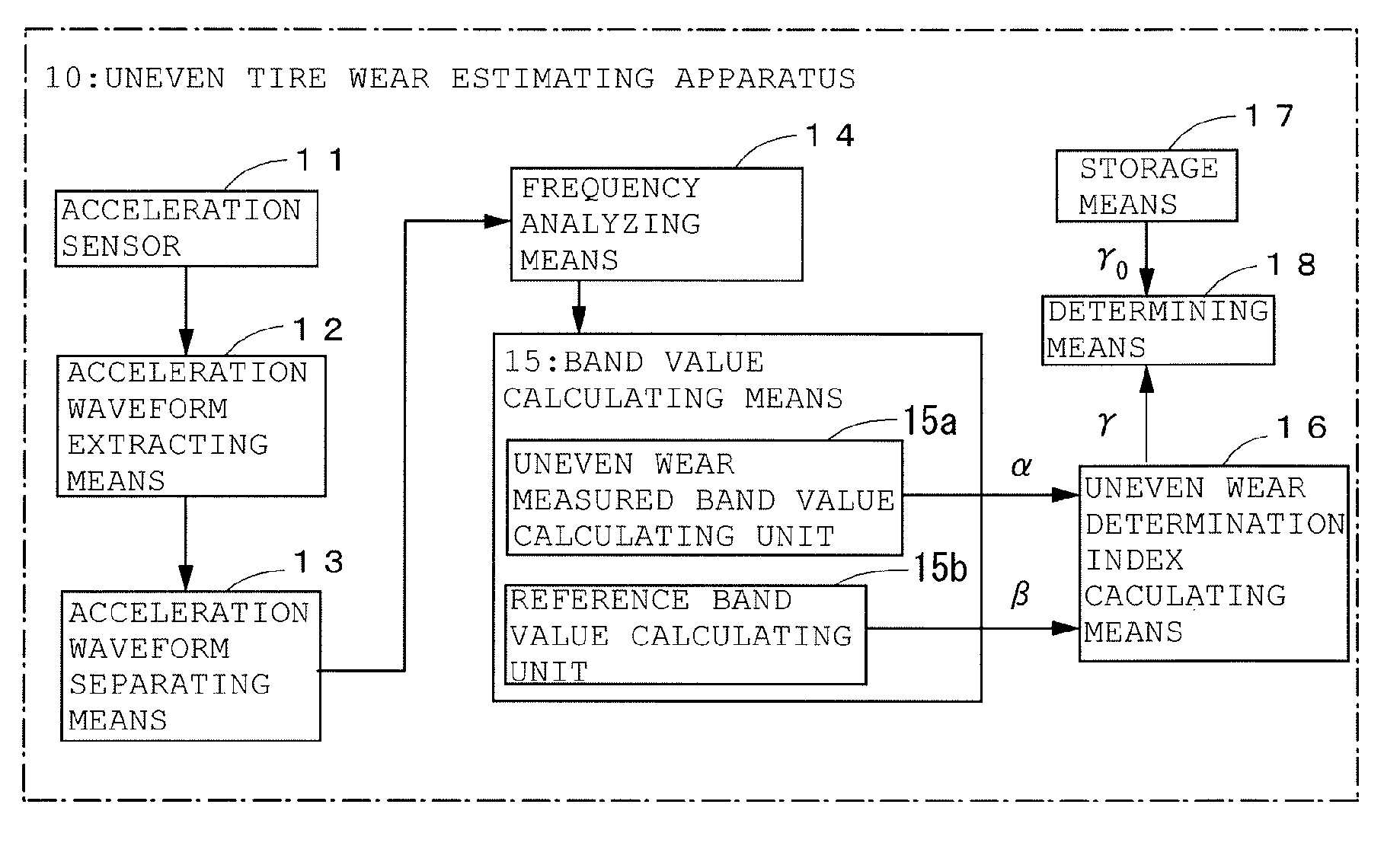
The present invention provides a technique to enhance the accuracy of estimating uneven wear in the tire shoulder while reducing the number of sensors. The invention uses the vibration level of a specific frequency range in the acceleration waveform to calculate an uneven wear measured band. This measured band is compared with a reference band where there is little noise and the vibration level is little affected by changes in uneven wear. An index is calculated to determine whether uneven wear is occurring in the edge of the tire shoulder, and this index is used to estimate changes in uneven wear. This structure allows for accurate estimation of uneven wear in the edge of the tire shoulder with a fewer number of sensors and less effect of changes in the vehicle's traveling speed.

Problems solved by technology

A tire gets worn in the tread surface as it runs from having friction with the road surface.
However, at the time of cornering, acceleration, or deceleration, lateral or fore-aft forces in relation to the traveling direction of the vehicle may work on tires.
As a result, there occur differences in the amount of wear between the central part and the shoulder parts of the tire tread.
As these uneven wears accumulate, a tire may have an extremely worn edge of the tire shoulder.
A tire having an extreme uneven wear, if it keeps on being used continuously, may eventually fail to deliver its primary performance.
Especially with winter tires, a problem that frequently arises is a lost grip on the road surface.
Also, an unevenly worn tire has a shape of the contact patch that is deviant from ideal.
Hence, such a tire will experience a greater loss of fuel economy performance than a normally worn tire having an evenly worn tread surface.

Method used


Image

  • Method and apparatus for estimating uneven tire wear
  • Method and apparatus for estimating uneven tire wear
  • Method and apparatus for estimating uneven tire wear

Examples


example

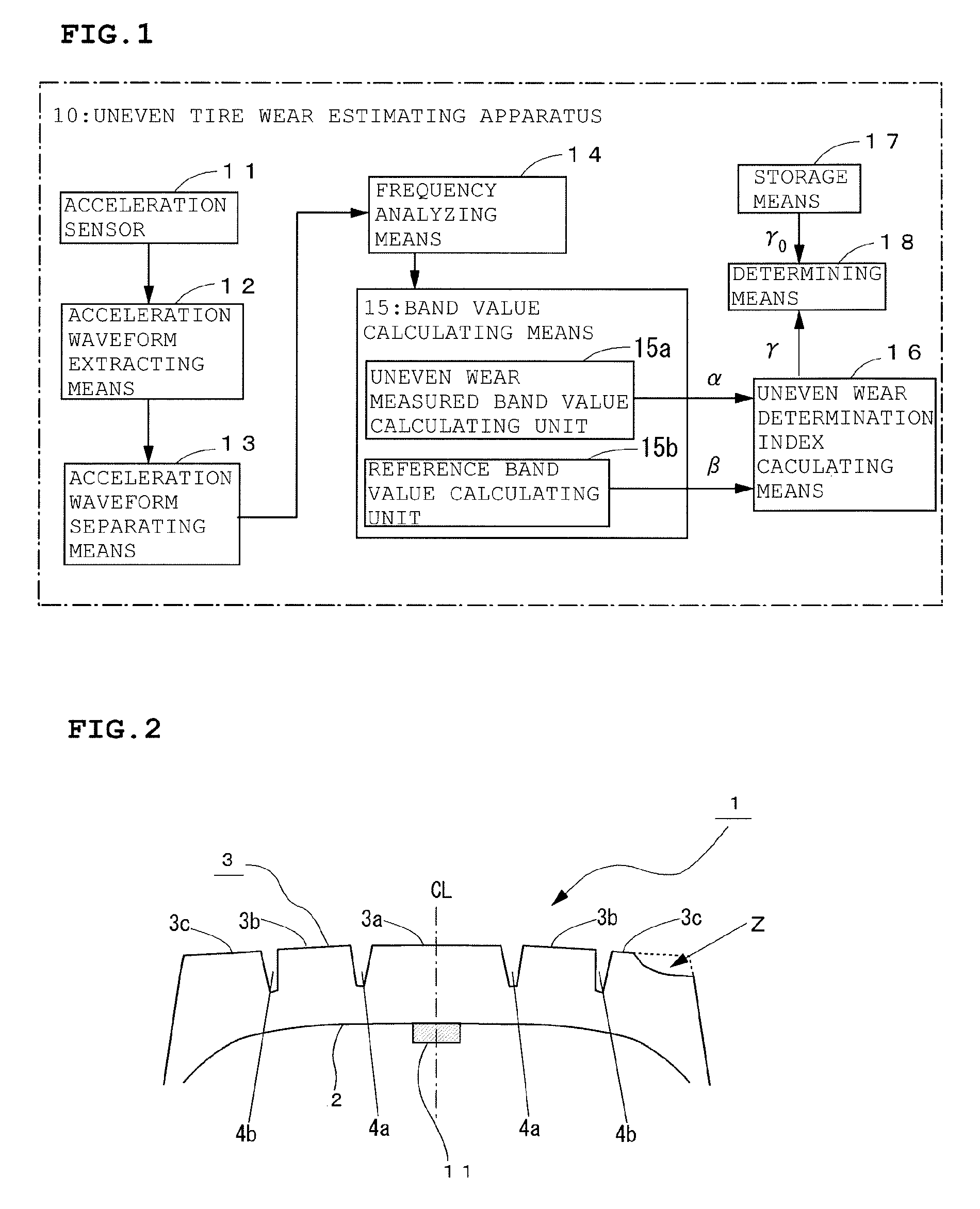
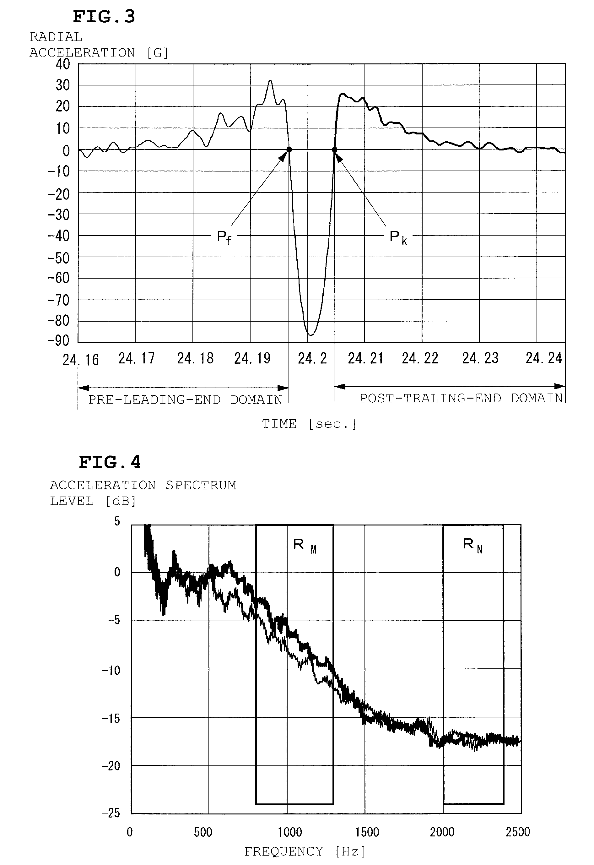
[0055]A vehicle fitted with a test tire having an acceleration sensor disposed at the axial center on the inner liner was prepared. The acceleration sensor was so disposed to have the detection direction in the radial direction of the tire. While the vehicle was operated at speeds of 60 km / hr to 80 km / hr, the radial acceleration waveforms and the frequency spectrums of the post-trailing-end waveforms were obtained by the storage and computing units mounted on the vehicle body for processing the output signals of the acceleration sensor. FIG. 3 shows a radial acceleration waveform when the test vehicle was operated at a speed of 80 km / hr. FIG. 4 shows frequency spectrums of post-trailing-end waveforms.

[0056]The size of the test tire was 315 / 70R22.5.

[0057]Also, two types of vehicles “loaded vehicle” and “half-loaded vehicle” were operated as the test vehicle, and the effects of loading were investigated. The load of the “loaded vehicle” was 2.85 tons, and that of the “half-loaded vehi...


PUM

PropertyMeasurementUnit
frequencyaaaaaaaaaa
frequencyaaaaaaaaaa
speedsaaaaaaaaaa

Abstract

A method and an apparatus for estimating uneven wear in the tire shoulder with high accuracy using a fewer number of sensors are provided. An uneven tire wear estimating apparatus includes an acceleration sensor (11) disposed on an inner surface of a tire tread for measuring radial acceleration, an acceleration waveform extracting means (12) for extracting an acceleration waveform in a post-trailing-end domain from output signals of the acceleration sensor, means for calculating a vibration level α of an uneven wear measured band and a vibration level β of a reference band from the extracted acceleration waveform, an uneven wear determination index calculating means (16) for calculating an uneven wear determination index γ, which is an index for determining au uneven wear, from the vibration level α and the vibration level β, and a determining means (18) for determining whether an uneven wear is occurring in an edge of the tire shoulder from the value of the uneven wear determination index γ.

Description

BACKGROUND OF THE INVENTION[0001]1. Field of the Invention[0002]The present invention relates to a method and apparatus for estimating whether an uneven wear is occurring in an edge of the tire shoulder from output signals of an acceleration sensor disposed on an inner surface side of the tire tread.[0003]2. Description of the Related Art[0004]A tire gets worn in the tread surface as it runs from having friction with the road surface. From the viewpoint of tire performance, it is desirable that the tread surface wears away evenly, thus causing no significant change in the shape of the contact patch (footprint). However, at the time of cornering, acceleration, or deceleration, lateral or fore-aft forces in relation to the traveling direction of the vehicle may work on tires. As a result, there occur differences in the amount of wear between the central part and the shoulder parts of the tire tread.[0005]As these uneven wears accumulate, a tire may have an extremely worn edge of the t...

Claims


Application Information

Patent Timeline
Patent Type & Authority Applications(United States)
IPC IPC(8): B60C11/24G01N29/44G01M17/02
CPCB60C11/243G01M17/025G01N2291/0235G01N2291/0289G01N29/4436B60C11/246
Inventor MASAGO, TAKESHI
Owner BRIDGESTONE CORP
Learn More