Spin control mechanism and spin device
a technology of spin control and spin device, which is applied in the direction of snap-action arrangement, generator/motor, and semiconductor/solid-state device details, etc., can solve problems such as affecting the normal operation of electronic devices
- Summary
- Abstract
- Description
- Claims
- Application Information
AI Technical Summary
Benefits of technology
Problems solved by technology
Method used
Image
Examples
first embodiment
[0039]A spin device according to the present embodiment will be described with reference to FIG. 1. FIG. 1 is a schematic view illustrating a configuration of a spin device according to an embodiment. (A) in FIG. 1 is a perspective view and (B) in FIG. 1 is a side sectional view.
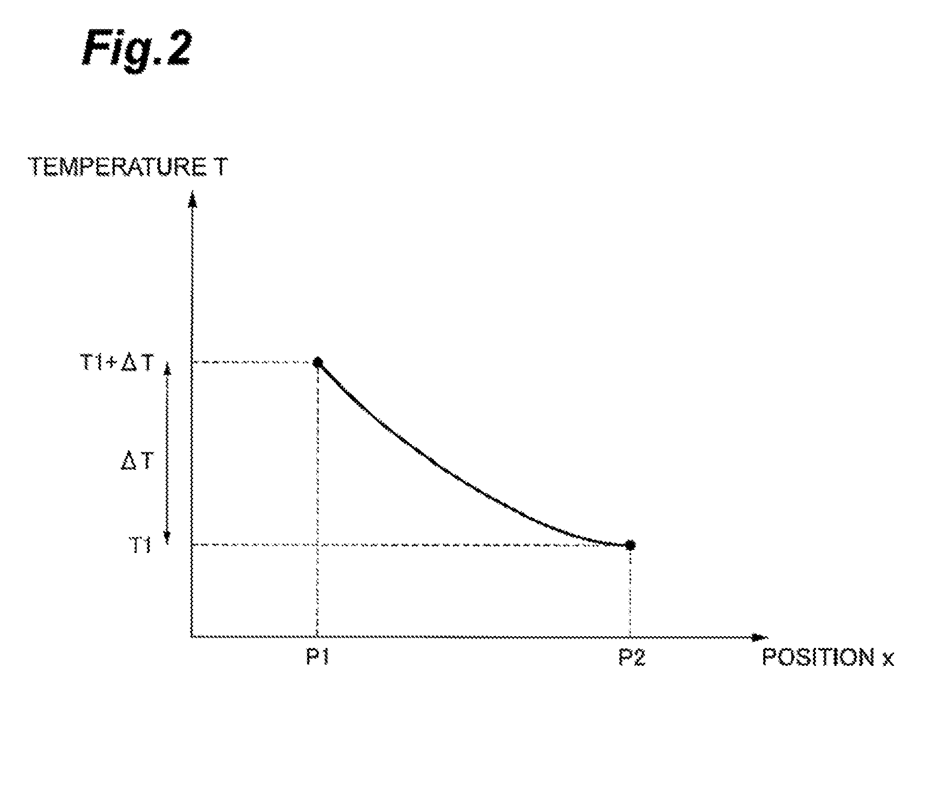
[0040]The spin device is a nanoscale device that reverses a magnetic moment using a spin current. Here, as an example of the spin device, a spin device that reverses the magnetic moment by application of a so-called spin Seebeck effect will be described. The spin Seebeck effect is a phenomenon in which the spin current is generated when a temperature difference is given to a magnetic body.
[0041]As illustrated in FIG. 1, the spin device 10 includes a spin control mechanism 1. The spin control mechanism 1 includes a spin portion 2 and a first channel portion 4.
[0042]The spin portion 2 has a magnetic moment 3 that can be reversed and rotated. That is, the spin portion 2 is configured from a magnetic body. The s...
second embodiment
[0051]A spin device 10 according to a second embodiment includes a spin control mechanism 1 similar to the spin device according to the first embodiment. The spin device 10 of the second embodiment is different from the spin device of the first embodiment in that the spin device 10 of the second embodiment is a spin motor by application of a so-called spin valve structure. Therefore, points overlapping with the description of the first embodiment are omitted, and the different point will be mainly described.
[0052]The spin device 10 according to the present embodiment will be described with reference to FIGS. 4 to 7. FIG. 4 is a perspective view of the spin device 10 according to an embodiment. FIG. 5 is a sectional view along line II-II of FIG. 4. FIG. 6 is an enlarged view of the spin device 10 according to an embodiment. FIG. 7 is a schematic view for describing an operation principle of the spin device 10.
[0053]As illustrated in FIG. 4, the spin device 10 includes, for example, a...
third embodiment
[0067]A spin device 10 according to a third embodiment includes a spin control mechanism 1 similar to the spin device according to the first embodiment. The spin device 10 according to the third embodiment is different from the spin devices according to the first and second embodiments in that a so-called perpendicular-to-surface spin valve structure is included. Therefore, points overlapping with the description of the first and second embodiments are omitted, and the different point will be mainly described.
[0068]As illustrated in FIG. 9, the spin device 10 includes substrates 60 and 61, an antiferromagnetic layer 62, a pinned layer 63, an intermediate layer 64, a free layer 65, a first channel portion 4, and a potential difference generating portion 50, for example. The pinned layer 63, the intermediate layer 64, and the free layer 65 form a spin valve structure.
[0069]The substrate 60 can be formed of a semiconductor material of Si or gallium arsenide (GaAs), or a nonmagnetic met...
PUM
 Abstract
Description
Claims
Application Information
 - R&D
- Intellectual Property
- Life Sciences
- Materials
- Tech Scout
- Unparalleled Data Quality
- Higher Quality Content
- 60% Fewer Hallucinations
Browse by: Latest US Patents, China's latest patents, Technical Efficacy Thesaurus, Application Domain, Technology Topic, Popular Technical Reports.
© 2025 PatSnap. All rights reserved.Legal|Privacy policy|Modern Slavery Act Transparency Statement|Sitemap|About US| Contact US: help@patsnap.com


