Shimming assistance unit, shimming assistance method, MRI apparatus and magnet apparatus

a technology of shimming assistance and mri apparatus, applied in the direction of magnet equipment, instruments, applications, etc., to achieve the effect of more efficient shimming operation

Active Publication Date: 2016-05-26
FUJIFILM HEALTHCARE CORP
View PDF1 Cites 2 Cited by
  • Summary
  • Abstract
  • Description
  • Claims
  • Application Information

AI Technical Summary

Benefits of technology

[0047]According to the present invention, it is possible when an operator performs shimming, to promptly and appropriately determine an upper limit val

Problems solved by technology

The magnet used in the MRI apparatus generates a static magnetic field requiring an accuracy

Method used


Image

  • Shimming assistance unit, shimming assistance method, MRI apparatus and magnet apparatus
  • Shimming assistance unit, shimming assistance method, MRI apparatus and magnet apparatus
  • Shimming assistance unit, shimming assistance method, MRI apparatus and magnet apparatus

Examples


Embodiment Construction

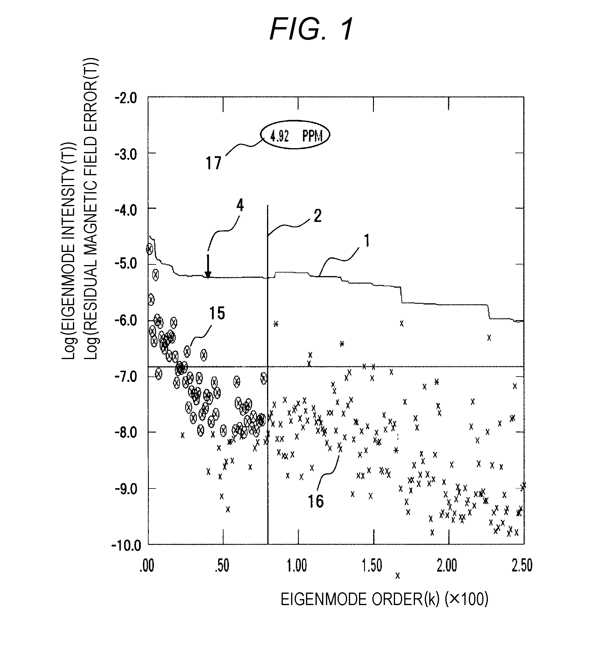
[0054]Hereinafter, embodiments of the present invention will be described with reference to the drawings. First, a method for calculating the residual magnetic field distribution Bres will be described.

[0055]Fundamental portions of the methods for calculation according to the present embodiment are based on the methods described in Patent Literature 1. Accordingly, description of the above-described TSVD method and of Formulas (1) to (5) will generally be applied to the present embodiment.

[0056]In the present embodiment, Formulas (1) to (5) are solved first so as to obtain Formula (6) for calculating the residual magnetic field distribution Bres.

Bres=Ber-A·M=Ber-A·{Σ(-vj·Cj / λj)}(6)

[0057]This Formula signifies that performing shimming once would improve the error magnetic field distribution Ber to be the residual magnetic field distribution Bres indicated in Formula (6).

[0058]Accordingly, in the present embodiment, the residual magnetic field distribution Bres is treated as a functio...


PUM


Abstract

The shimming work assistance unit performs singular value decomposition of a response matrix, which represents the relationship between an error magnetic field distribution and an adjusted magnetic moment placement distribution. From the multiple eigenmodes obtained, the eigenmodes are selected and added one by one in order from the eigenmode with the highest singular value, and the residual magnetic field error, which represents the fluctuation range of the difference between the magnetic field distribution, generated by the placement of the shimming magnetic moments corresponding to said eigenmode, and the error magnetic field distribution, is displayed on a display unit as a function graph of eigenmode order (line graph (1)).

Description

TECHNICAL FIELD[0001]The present invention relates to a shimming assistance unit, a shimming assistance method for a magnet apparatus that needs precise magnetic field distribution adjustment, and a nuclear magnetic resonance tomographic imaging apparatus (hereinafter, referred to as magnetic resonance imaging (MRI) apparatus) that includes the shimming assistance unit.BACKGROUND ART[0002]An MRI apparatus uses a magnet of mainly a superconducting magnet. In some cases, however, it uses a permanent magnet and a normal conducting magnet. The magnet used in the MRI apparatus generates a static magnetic field requiring an accuracy which has a variation of about one millionth of a magnetic field intensity come to a problem.[0003]The magnetic fields used in the MRI apparatus are broadly classified into the following three types.[0004](1) A magnetic field that is temporally and spatially constant and that normally has an intensity of 0.1 to several teslas or more, having the amount of vari...

Claims


Application Information

Patent Timeline
IPC IPC(8): G01R33/3873G01R33/565A61B5/055
CPCG01R33/3873G01R33/5659A61B5/055H01F7/202G01R33/3875
Inventor ABE, MITSUSHI
Owner FUJIFILM HEALTHCARE CORP
Why Eureka
Try Eureka