
Methods and systems for enhancing control of power plant generating units

a technology for enhancing control and power plant generating units, applied in adaptive control, process and machine control, instruments, etc., can solve the problems of affecting the actual output and efficiency of the power plant, increasing the cost of variable variables, and complex derivation methods

Active Publication Date: 2016-09-08
GENERAL ELECTRIC CO
View PDF8 Cites 64 Cited by
  • Summary
  • Abstract
  • Description
  • Claims
  • Application Information

AI Technical Summary

Benefits of technology

The patent describes a method for optimizing the output of a power block that includes multiple gas turbines. The method involves receiving data about the operating parameters of each gas turbine, identifying different ways to operate the power block based on the data, predicting the performance of the power block based on the operating modes, and determining the cost of each mode. The method then selects the most cost-effective mode for operation. The technical effect of this method is to improve the efficiency and overall performance of multiple gas turbines in generating power.

Problems solved by technology

In a combined-cycle power plant in which waste heat from a fuel burning generator is used to produce steam to power a supplemental steam turbine, an incremental variable cost curve may also be obtained with known techniques, but its derivation may be more complex.
However, the actual output and efficiency of a power plant is impacted by external factors, such as variable ambient conditions, that cannot be fully anticipated.
As will be appreciated, the complexity of such systems and the variability of operating conditions make it difficult to predict and control performance, which often result in inefficient operation.
Machine degradation that occurs over time is another difficult to quantify fact, which may have a significant effect on the performance of the generating units.
If a gas turbine or a component thereof reaches its starts limit before its hours limit, it must be repaired or replaced, even if it has hours-based life remaining Hours-based life in a gas turbine may be prolonged by reducing firing temperature, but this reduces efficiency of the gas turbine, which increases cost of operation.
Conversely, increasing the firing temperature increases efficiency, but shortens gas turbine life and increases maintenance and / or replacement costs.
Given the complexity of modern power plants, particularly those having multiple generating units, and the market within which it competes, power plant operators continued to struggle to maximize economic return.
For example, grid compliance and dispatch planning for a power plant is adversely impacted by controlling thermal generating units in an overly-static manner, i.e., using static control profiles, such as heat rate curves gathered derived from only periodic performance tests.
Between these periodic updates, turbine engine performance may change (e.g., from degradation), which may affect start-up and load performance.
Moreover, intraday changes in the external factors, without accounting for the same in the turbine control profiles, may lead to inefficient operation.
To compensate for this type of variability, power plant operators often become overly conservative in planning for future operation, which results in underutilized generating units.
Other times, plant operators are forced to operate units inefficiently to satisfy over-commitments.
Without identifying the short-term inefficiencies and / or long-term deterioration as each is realized, the conventional control systems of power plants either have to be retuned frequently, which is an expensive process, or conservatively operated so to preemptively accommodate component deterioration.
The alternative is to risk violating operational boundaries that leads to excessive fatigue or failure.
Similarly, conventional power plant control systems lack the ability to most cost-effectively accommodate changing conditions.
As will be appreciated, this results in power plant utilization that is often far from optimal.

Method used


Image

  • Methods and systems for enhancing control of power plant generating units
  • Methods and systems for enhancing control of power plant generating units
  • Methods and systems for enhancing control of power plant generating units

Examples


Embodiment Construction

[0039]Example embodiments of the invention will be described more fully hereinafter with reference to the accompanying drawings, in which some, but not all embodiments are shown. Indeed, the invention may be embodied in many different forms and should not be construed as limited to the embodiments set forth herein; rather, these embodiments are provided so that this disclosure will satisfy applicable legal requirements. Like numbers may refer to like elements throughout.

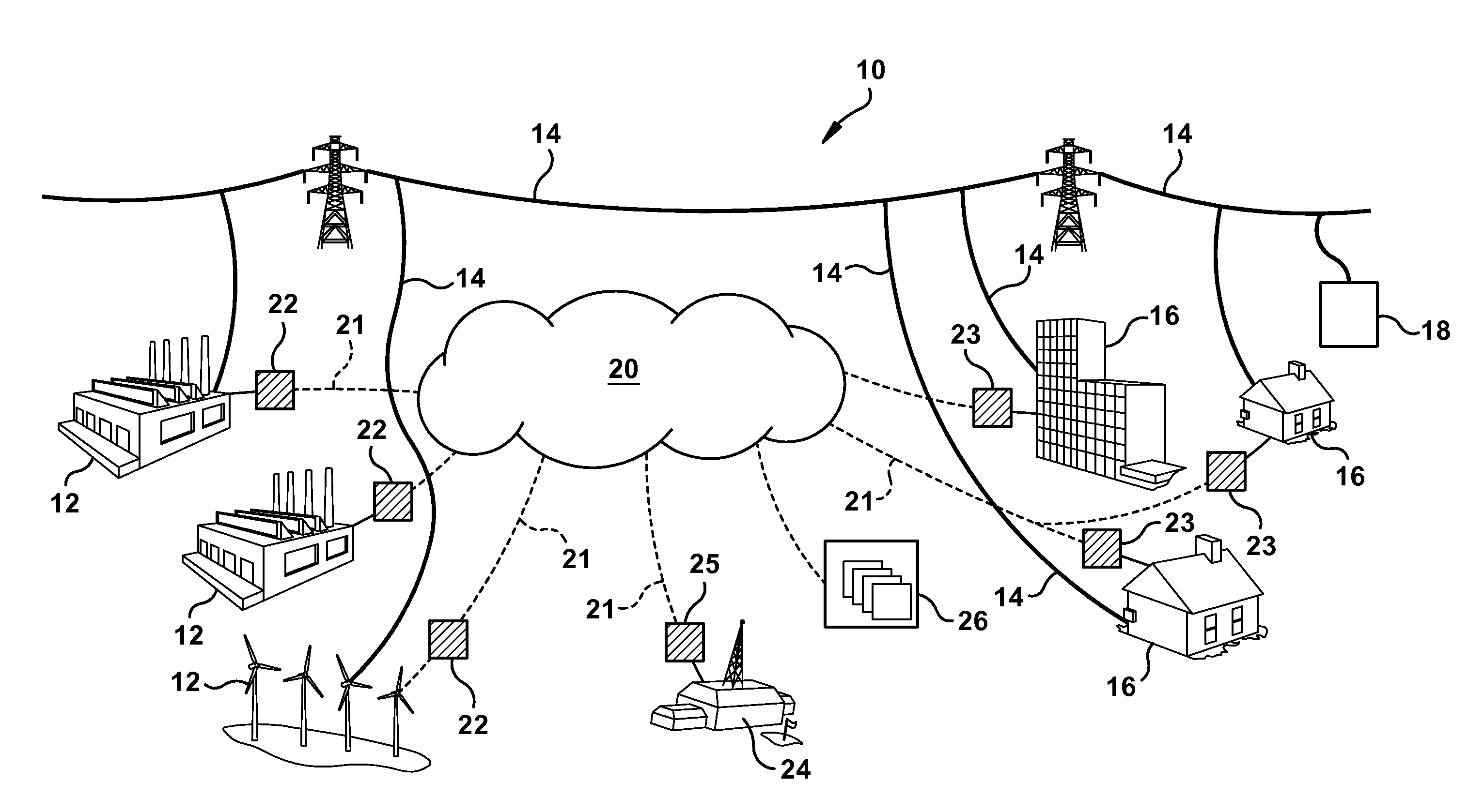
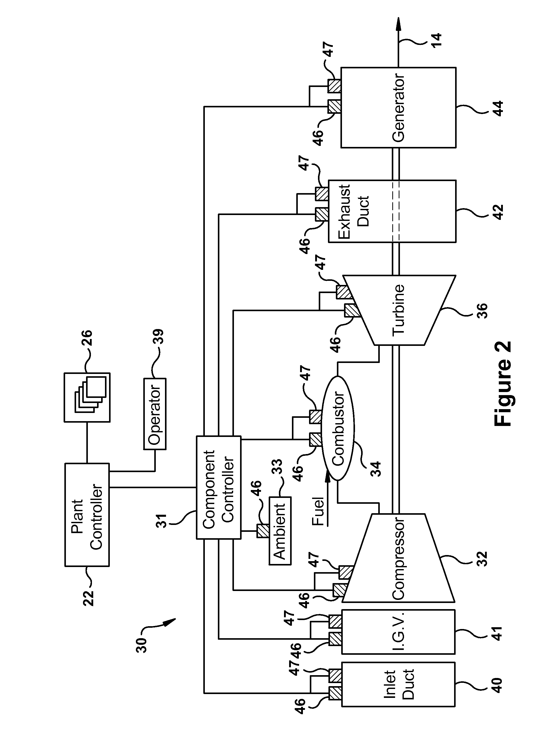
[0040]According to aspects of the present invention, systems and methods are disclosed which may be used to optimize the performance of power systems, power plants, and / or thermal power generating units. In exemplary embodiments, this optimization includes an economic optimization by which an operator of a power plant decides between alternative modes of operation so to enhance profitability. Embodiments may be utilized within a particular power system so to provide a competitive edge in procuring advantageous econom...


PUM


Abstract

A method for optimizing a generation of an output level over a selected operating period by a power block, wherein the power block comprises multiple gas turbines for collectively generating the output level. The control method may include: receiving current state data regarding measured operating parameters for each of the gas turbines of the power block; based on the current state data, defining competing operating modes for the power block; based on each of the competing operating modes, deriving a predicted value for a performance parameter regarding the operation of the power block over the selected operating period; determining a cost function and, pursuant thereto, evaluating the operation of the power block based on the predicted value of the performance parameter so to determine a projected cost; and comparing the projected costs from each of the optimized operating modes so to select therefrom an optimized operating mode.

Description

BACKGROUND OF THE INVENTION[0001]The invention of the present application relates generally to power generation and, more particularly, to methods and systems related to the economic and performance optimization and / or enhancement of power plants having thermal generating units.[0002]In electric power systems, a number of participants or power plants generate electricity that is then distributed over common transmission lines to residential and commercial customers. As will be appreciated, thermal generating units, such as gas turbines, steam turbines, and combined-cycle plants, are still relied on to generate a significant portion of the power such systems require. Each of the power plants within such systems include one or more power generating units, and each of these units typically includes a control system that controls operation, and, in case of power plants having more than one generating unit, the performance of the power plant as a whole. As an example, one of the responsi...

Claims


Application Information

Patent Timeline
Patent Type & Authority Applications(United States)
IPC IPC(8): F02C9/00G05B13/02
CPCG05B13/026F02C9/00G06Q10/04G06Q10/06G06Q50/06H02J3/46Y02E40/70Y04S10/50H02J3/466
Inventor TIWARI, AWADESH KUMARASATI, MAHESH KUMAR
Owner GENERAL ELECTRIC CO
Learn More