Diagnostic for in situ Deformation and Strain Measurements Applicable to Traumatic Internal Injury Investigation and Prevention

Active Publication Date: 2016-08-04
PETEL OREN E
View PDF1 Cites 4 Cited by
  • Summary
  • Abstract
  • Description
  • Claims
  • Application Information

AI Technical Summary

Benefits of technology

The present invention is a gage that can measure the deformation of soft tissue or soft tissue-simulants under an arbitrary loading condition. It is made with a substrate integrated or coated with x-ray contrast agents that can be introduced into the tissue-simulants of an ATD, headform, or within a biological system itself along an internal surface or plane in which the deformation is to be measured. The gage is monitored using fluoroscopic techniques to determine the time-resolved motion of the contrast materials. The contrast material must be integrated in a way that does not significantly impede the deformation of the tissue-simulant being measured, while adequately coupling the motion of the tissue-simulant to the contrast agents. The gage can be used to measure internal strain histories in tissue-simulants within ATDs and headforms to increase the reliability of the predictions of injury outcomes and provide a diagnostic that can improve the certification standards for personal protective equipment, replacing the unreliable accelerometer-based methods currently employed. The use of continuous or multi-anode x-ray sources and high-speed cameras, photodiodes, or similar optical detectors coupled to fluoroscopic screens to record the relative locations of the contrast agents can be necessary to ensure sufficient time resolution of the deformation history.

Problems solved by technology

The limitations of the current testing and certification methods related to protective equipment designed to protect against internal traumatic injuries, particularly head injuries, is evident from the prevalence of such injuries.

Method used


Image

  • Diagnostic for in situ Deformation and Strain Measurements Applicable to Traumatic Internal Injury Investigation and Prevention
  • Diagnostic for in situ Deformation and Strain Measurements Applicable to Traumatic Internal Injury Investigation and Prevention
  • Diagnostic for in situ Deformation and Strain Measurements Applicable to Traumatic Internal Injury Investigation and Prevention

Examples


first embodiment

3)

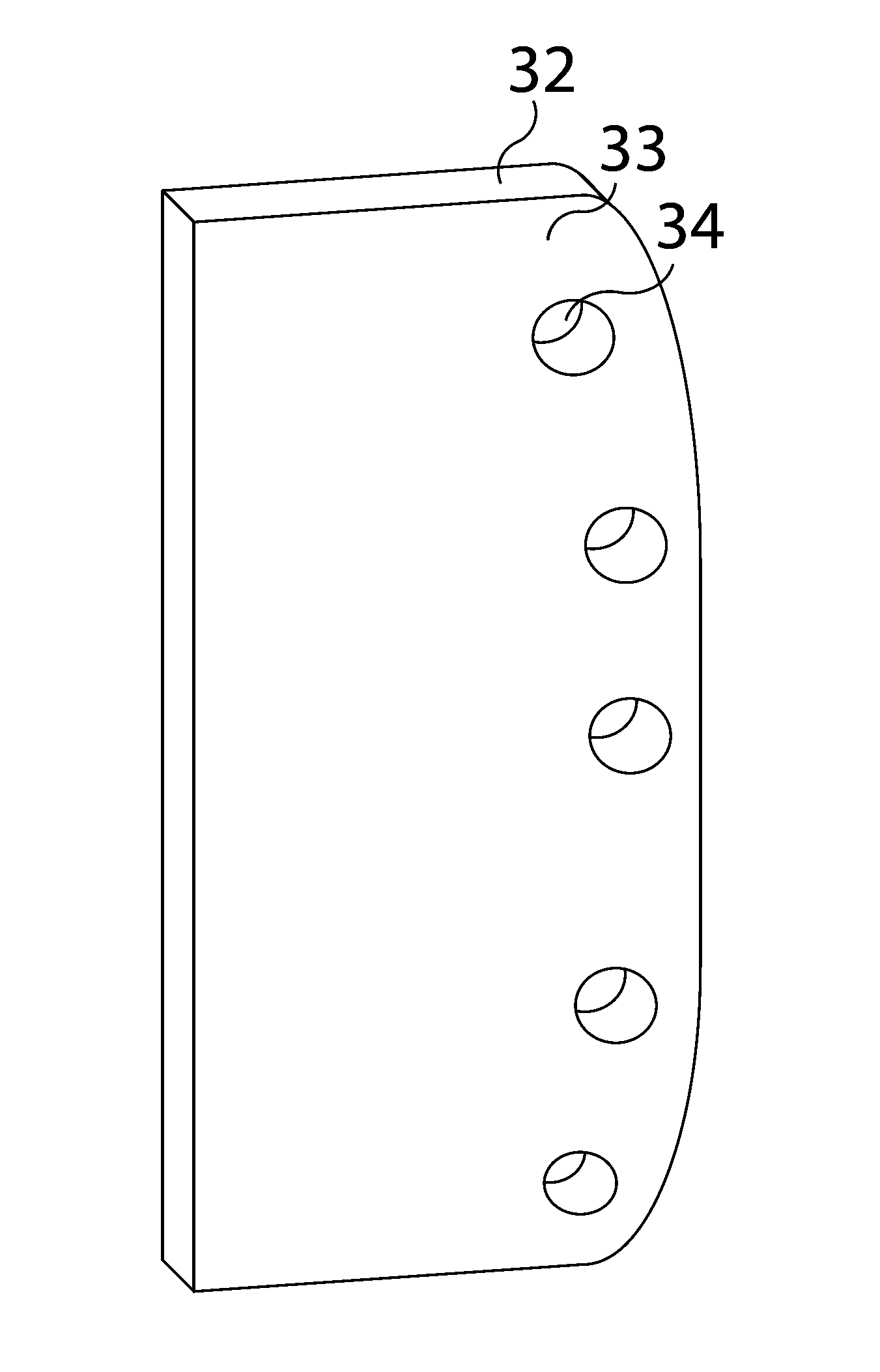
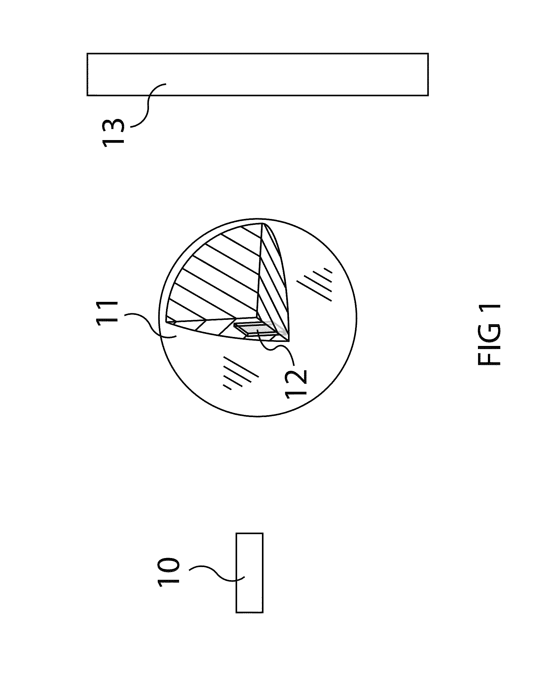
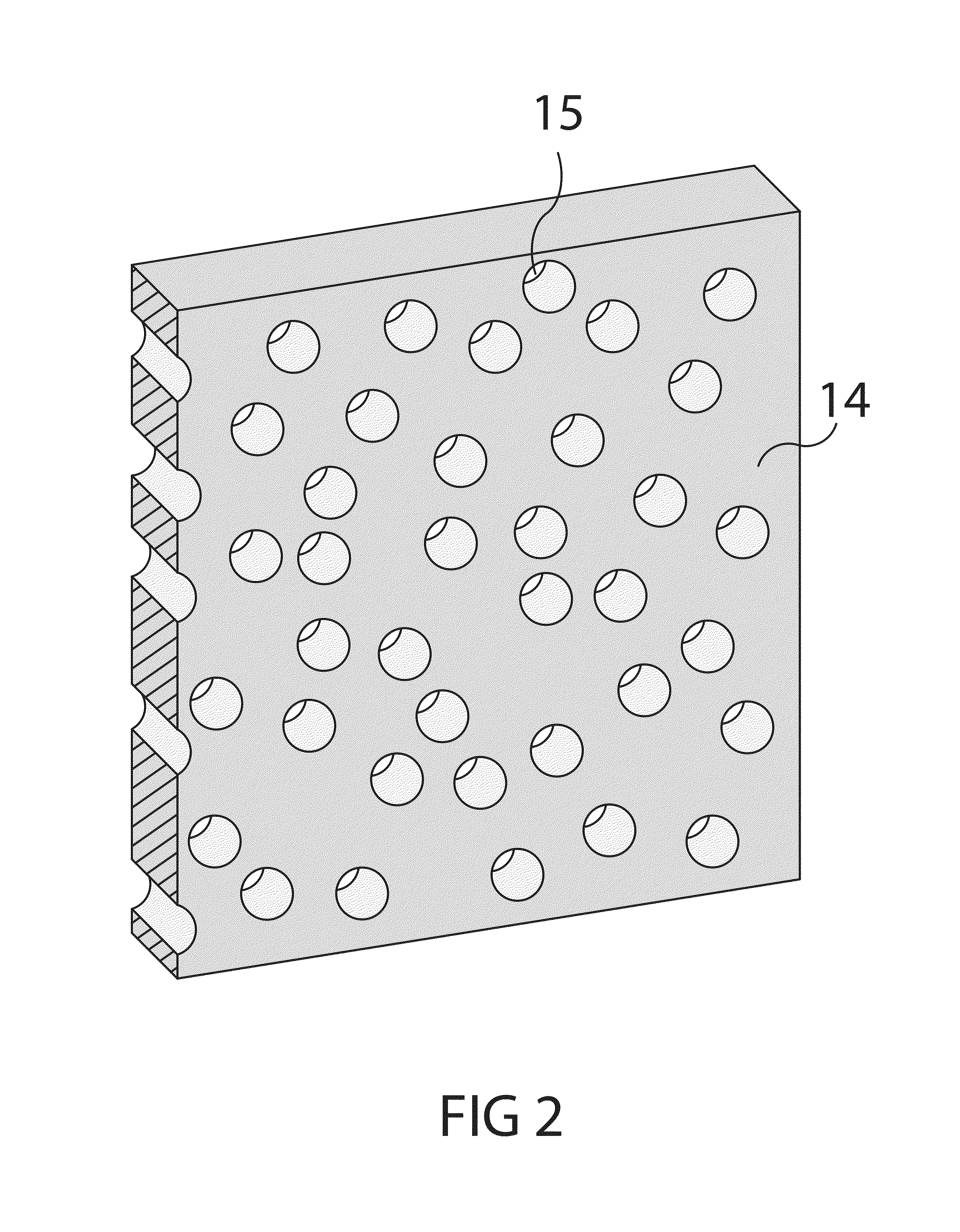
[0064]In its first embodiment, the gage 12 is introduced into an internal plane of the test material 11 (e.g., anthropomorphic soft-tissue simulating headform) that is to be loaded with any type of force and its deformation is investigated (FIG. 1) using radiographic videography techniques 10 / 13 (e.g., x-ray videography or fluoroscopy). In its first embodiment, the gage consists of a contrast agent that is mixed into a substrate material at a considerably fine scale (e.g., as a powder) with a volume fraction of at least 5% contrast agent 14. The substrate material could be any polymeric, elastomeric or other material that can be prepared as it is being mixed with the contrast agent to allow casting of the gage with a series of holes 15 as shown in FIG. 2.

[0065]The holes in the gage 15, the size of which will depend on the magnification and resolution of the imaging configuration, must be large enough to encompass at least 4 pixels on the digital receiver, with an equivalent averag...


PUM


Abstract

A diagnostic gage (12) that can be implemented into a tissue-simulating headform (17) or other anthropomorphic surrogate test device (11) as a means of determining the internal strain within the test surrogate. One embodiment of the gage consists of a matrix or substrate embedded with x-ray contrast agents (14) and a series of holes within the substrate (15) that provide contrasting markers in an x-ray image and a means of intimately coupling the gage to the test specimen. The relative motion of these contrasting markers can be monitored using x-ray fluoroscopy equipment (e.g., source (10) and detector (13)). This gage provides a means of determining the internal strain within a headform surrogate model for the purpose of evaluating the performance of helmets in terms of reducing the occurrence of concussion among other biomechanical injuries from trauma.

Description

CROSS-REFERENCE TO RELATED APPLICATIONS[0001]Not ApplicableFEDERALLY SPONSORED RESEARCH[0002]Not ApplicableSEQUENCE LISTING OR PROGRAM[0003]Not ApplicableBACKGROUND[0004]1. Field[0005]This application relates to a diagnostic gage designed to measure the internal deformation and strain history within soft-tissue anthropomorphic test devices as a means of evaluating the potential for an internal injuries from an external traumatic force application.[0006]2. Prior Art[0007]Internal traumatic injuries can result from various types of impacts, including scenarios in which the impacts do not result in a penetration of a person's body. Examples of such internal traumatic injuries that do not involve penetration are concussions as well as other head injuries within the traumatic brain injury spectrum and blunt impact trauma. Being in close proximity to an explosion can similarly result in internal traumatic injuries from blast wave exposure, targeting specific organs such as the lungs and b...

Claims


Application Information

Patent Timeline
IPC IPC(8): A61B6/00A42B3/04
CPCA61B6/481A61B6/50A61B6/485A42B3/046A42B3/06G01B15/06G01N23/04G09B23/30A61B5/1127A61B5/1128A61B6/501A61B6/584A61B2562/164A61B2576/026
Inventor PETEL, OREN E.
Owner PETEL OREN E
Why Eureka
Try Eureka