Scanning beam emitting device, laser radar device and laser radar detection method

A technology of emitting device and scanning beam, applied in the field of scanning beam emitting device, can solve the problems of low precision, limited scanning range, complicated process, etc., and achieve the effects of high integration, increased spatial azimuth resolution, and simple control circuit

Active Publication Date: 2019-01-25
TSINGHUA UNIV
View PDF7 Cites 13 Cited by
  • Summary
  • Abstract
  • Description
  • Claims
  • Application Information

AI Technical Summary

Problems solved by technology

However, the current optical phased array is still in the development stage, and there are many key technical problems that have not been resolved, which cannot meet the actual engineering needs.
[0004]The current phased array laser radar has the following problems: the optical phased array is limited by the manufacturing process, and when the distance between the radiation elements is greater than half the wavelength, it will cause the grating lobe problem and the The scanning range is limited; the corresponding two-dimensional phased array element control circuit is complex when the laser radar performs two-dimensional scanning, resulting in large volume, complex process, high cost, and low precision, making it impossible to realize large area array applications

Method used


Image

  • Scanning beam emitting device, laser radar device and laser radar detection method
  • Scanning beam emitting device, laser radar device and laser radar detection method
  • Scanning beam emitting device, laser radar device and laser radar detection method

Examples


Embodiment Construction

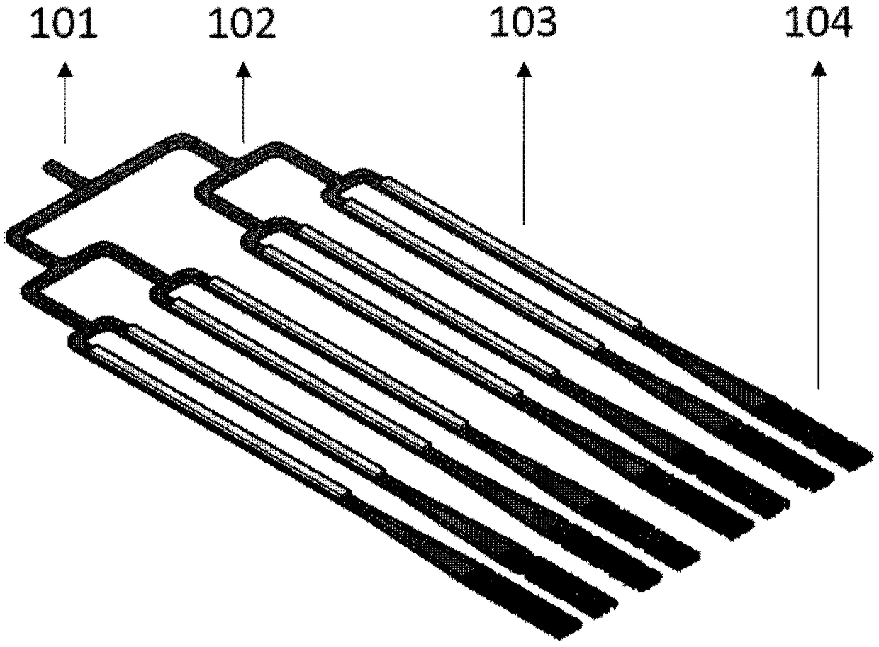
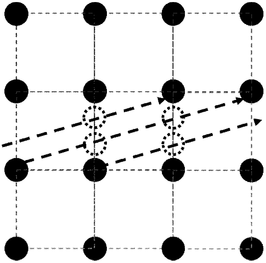
[0032] The disclosure provides a scanning beam emitting device, a laser radar device and a detection method. In the scanning beam emitting device, the coupling beam splitting grating array is combined with the one-dimensional optical modulator array, and the coupling beam splitting grating array The light is coupled to the free space and divided into a two-dimensional beam array with uniform intensity. The modulation of the optical phase is realized by controlling the one-dimensional light modulator array, so that the two-dimensional beam array scans in a small range in a specific one-dimensional direction, covering the origin The space between the arrays, so as to realize the effect of two-dimensional scanning under the condition of one-dimensional scanning, the control circuit is simple, the integration degree is high, and it is beneficial to increase the spatial orientation resolution of the laser radar.

[0033] In order to make the purpose, technical solutions and advantag...


PUM


Abstract

The invention discloses a scanning beam emitting device, a laser radar device and a laser radar detection method, wherein the scanning beam emitting device comprises an input waveguide, a beam splitting waveguide array, a one-dimensional light modulator array and a coupled beam splitting grating array; the beam splitting waveguide array is connected with the input waveguide, and used for uniformlyand equally dividing light in the input waveguide into multiple channels of light; the one-dimensional light modulator array is connected with the beam splitting waveguide array, and used for performing phase modulation on multiple channels of light in the beam splitting waveguide array; the coupled beam splitting grating array is connected with the one-dimensional light modulator array, and usedfor coupling light in the beam splitting waveguide array into a free space and outputting a two-dimensional beam array having uniform strength; and furthermore, under the modulation of the one-dimensional light modulator array, the beam array can perform scanning along the one-dimensional direction. The scanning beam emitting device is simple in control circuit and high in integration degree; andfurthermore, the spatial azimuth resolution of a laser radar is easily increased.

Description

technical field [0001] The disclosure belongs to the technical field of laser radar, and relates to a scanning beam emitting device, a laser radar device and a detection method. Background technique [0002] Time-of-flight lidar is similar to microwave radar. By measuring the time difference between the emitted laser pulse and the received laser pulse reflected by the object, the distance to the target in a specific azimuth is obtained, and the three-dimensional reconstruction of the target area is realized. Due to the high laser frequency and energy concentration, LiDAR has strong anti-electromagnetic interference ability and high accuracy of angle measurement and distance measurement. [0003] In the prior art, mechanical scanning lidar is widely used due to its large scanning range and low light loss, but its scanning speed is slow, its volume and weight are large, and its cost is high. Phased array lidar achieves flexible beam pointing through beam control, small size a...

Claims


Application Information

Patent Timeline
Patent Type & Authority Applications(China)
IPC IPC(8): G01S17/89G01S7/484
CPCG01S7/484G01S17/89
Inventor 郝智彪刘雅琦汪莱熊兵孙长征王健李洪涛韩彦军罗毅
Owner TSINGHUA UNIV
Why Eureka
Try Eureka