Detector of ionizing radiation enabling a coherent digital image

Active Publication Date: 2016-07-21
ADVACAM SRO +1
View PDF9 Cites 9 Cited by
  • Summary
  • Abstract
  • Description
  • Claims
  • Application Information

AI Technical Summary

Benefits of technology

The detector described in this patent is designed to capture a continuous and coherent image of a scanned object without the need for special hardware or software resources. It does this by using a sensor layer that is active over its entire area, including the edges of the sensor layer. The detector segments are positioned tightly next to each other, minimizing the gap between them and creating a complete image.

Problems solved by technology

For hybrid semiconductor pixel detectors, the problem arises of creating a coherent image of a larger scanned object, because the maximum size of the detection area of one hybrid detector is limited by its maximum technologically achievable size.
For larger areas, the probability of manufacturing defects is already high, and production becomes inefficient.
The problem which must be addressed in mosaic structure of the detection area is that the known solutions of detector segments use a sensor layer which have inactive (non-sensitive) edges and which therefore do not permit the detection of radiation and the design of an image from the entire area of the sensor layer.
This gives rise to a so-called dead edge zone, or frames around the perimeter of individual detector segments that make it impossible to create a coherent image but divide the image into individual image segments from individual chips.
The disadvantage of this solution lies in the fact that the operation of the detector requires calibrated equipment for producing the relative movement and appropriate special software, so the manufacture and operation of such a detector is therefore complicated and costly.
Overlapping insensitive edges also reduces the sensitivity of the detector in the marginal areas.
These dead zones, in the creation of a coherent image, must be digitally blurred and overlapped, which, however, when used in medicine or flaw detection is a serious problem in terms of inaccuracies of the resulting image.
The individual segments of the sensor layer are produced by cutting material from larger boards, which causes damage to the material in the area adjacent to the cut, so this narrow region along the edge, respectively sides, of a square or rectangular segment is inactive and cannot detect radiation.
Solutions according to US 2001 / 0012412 A1 may eliminate some of the disadvantages of the solutions according to WO 95 / 33332, but they do not eliminate the fundamental problem of the existence of dead zones in the continuous image of the scanned object, so therefore a coherent and realistic image of the scanned object is not created by this solution.
Another disadvantage of the solution according to US 2001 / 0012412 A1 consists in that although the carriers of individual detector segments are fixed in the matrix of the detector surface removably, it is only in a specific and fixed position which does not allow for the positioning of detector segments to the side to limit their mutual lateral clearance.
This creates gaps between the detector segments which form other dead zones that prevent the creation of a contiguous digital image.

Method used


Image

  • Detector of ionizing radiation enabling a coherent digital image
  • Detector of ionizing radiation enabling a coherent digital image
  • Detector of ionizing radiation enabling a coherent digital image

Examples


Embodiment Construction

OF THE PREFERRED EMBODIMENTS OF THE INVENTION

[0050]It should be understood that the specific examples of the invention described and illustrated below are presented for illustration and not as a limitation of the examples of the invention to these examples alone. Professionals familiar with the state of technology shall find, or will be able to determine through routine experimentation, a greater or smaller number of equivalents of the specific realization of the invention which are described herein. These equivalents shall also be included in the scope of the following claims.

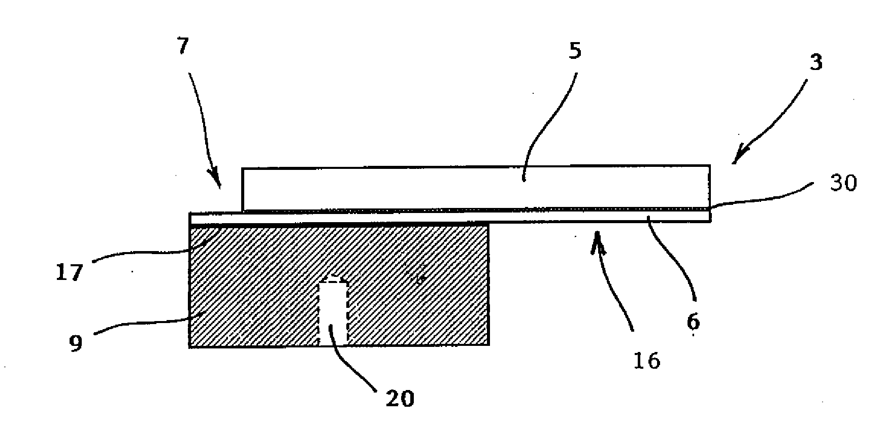
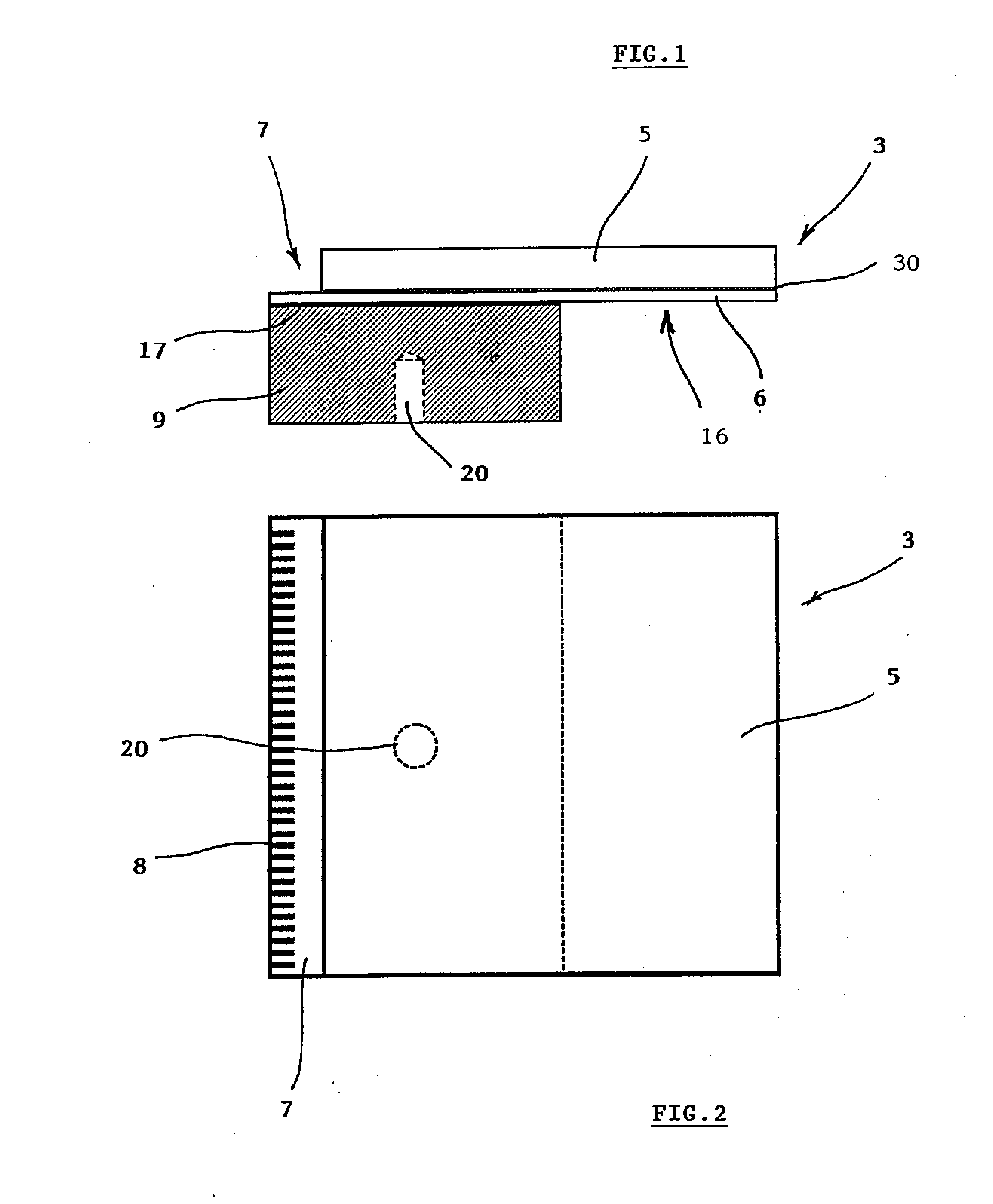
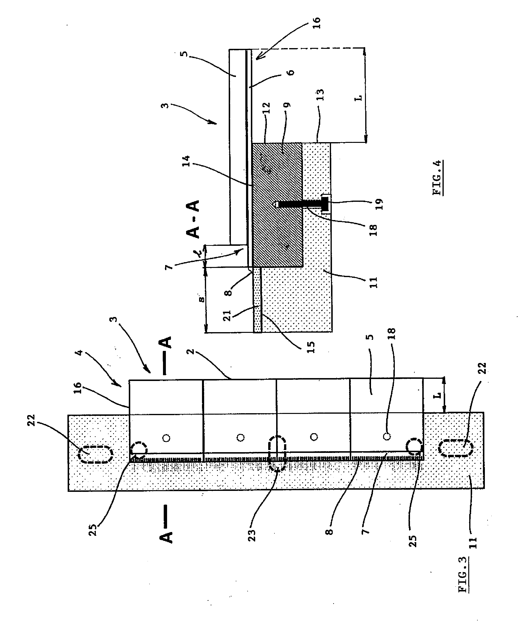
[0051]The detector 1 shown in FIG. 1 to FIG. 9 is formed as a detector of X-rays, but with the use of suitable sensor layers 5 may also be adapted for the detection of other types of radiation. The base of the detector 1 is composed of a matrix 10 made of an aluminum alloy which carries the mosaic of detector segments 3 arranged in individual rows 4. Each detector segment 3 contains a square semiconductor pixe...


PUM


Abstract

A detector of ionizing radiation, e.g. x-ray radiation, allowing for the creation of a continuous digital image of a scanned object. The detection surface is formed by a mosaic of detector segments arranged in a matrix and consisted of a sensor layer arranged on a chip reader with the formation of tiers to engage an adjacent detector segment. The sensor layer is active over its entire area, and the matrix is provided with a means for positioning the detector segments to define their mutual lateral clearance less than the size of one pixel. The positioning means preferably comprises a carrier of rows. The resulting detection surface is active over its entire area and allows for the direct creation of continuous digital image without dead zones.

Description

FIELD OF THE INVENTION[0001]The invention relates to a detector of ionizing radiation for creating a coherent digital image of the scanned object, usable in particular in the field of flaw detection, non-destructive materials testing, product quality control, and also in medicine and biotechnology.BACKGROUND OF THE INVENTION[0002]Detectors of ionizing radiation for creating an image of a scanned object, namely detectors of X-rays, gamma rays, beta rays or other ionizing radiation are used not only in medicine, biology and biotechnology, but they are also widely used in industrial applications where they are particularly used as a means of non-destructive testing of any objects from the detection of defects in materials for quality control, to customs and police or security checks on delivered goods and transported objects.[0003]The image of the scanned object is transmitted to a display area, either directly (projection display) or by data from the detector being computer-processed,...

Claims


Application Information

Patent Timeline
IPC IPC(8): G01T1/29G01T1/24G01N23/041
CPCG01T1/243G01T1/2928
Inventor JAKUBEK, JAN
Owner ADVACAM SRO
Why Eureka
Try Eureka