
Separation of interference pulses from physiological pulses in a pressure signal

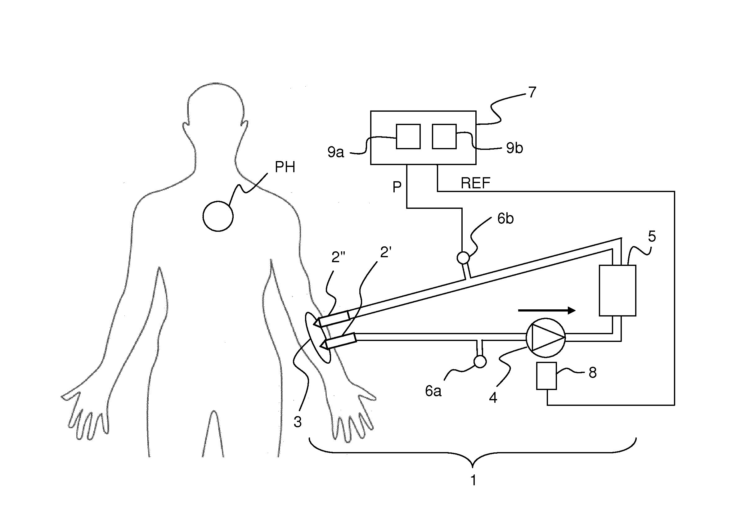
a pressure signal and interference pulse technology, applied in the field of pressure signal processing techniques, can solve the problems of difficult to properly remove e.g. pump pulses, difficult to properly remove them, so as to improve the representation of improve the representation of b pulse sequence, and improve the sequence of a pulse sequence

Active Publication Date: 2016-07-21
GAMBRO LUNDIA AB
View PDF10 Cites 22 Cited by
  • Summary
  • Abstract
  • Description
  • Claims
  • Application Information

AI Technical Summary

Benefits of technology

The invention has been designed to improve the representation of pulses in a signal segment by subtracting a template signal from the signal segment to generate a new difference signal. This iterative approach can significantly improve the accuracy of the difference signals and the template signals, and accurately represent the timing, shape, and magnitude of the pulses in the signal segment. The signal segment may contain different types of pulses, which can also be represented in the difference signal after each template subtraction.

Problems solved by technology

Serious conditions may e.g. arise if the EC circuit is disrupted downstream of the blood pump, e.g. by a Venous Needle Dislodgement (VND) event, in which the venous needle comes loose from the blood vessel access.
Such a disruption may cause the subject to be drained of blood within minutes.
It may be a challenging task to properly remove e.g. the pump pulses, since the rate of the physiological pulses and the rate of the blood pump, i.e. the blood flow through the EC circuit, may change over time.
If the rate of physiological pulses matches the rate of pump pulses, it is not unlikely that the filtering will remove also the physiological pulses, causing the monitoring technique to fail.
Filtering is also rendered difficult by the fact that the pump pulses generally are much stronger than the physiological pulses in the pressure signal.

Method used


Image

  • Separation of interference pulses from physiological pulses in a pressure signal
  • Separation of interference pulses from physiological pulses in a pressure signal
  • Separation of interference pulses from physiological pulses in a pressure signal

Examples


implementation example

[0127]Below follows a brief mathematical description of an implementation of the principles described in the foregoing. The description is given with reference to the steps in FIG. 7.

Step S2

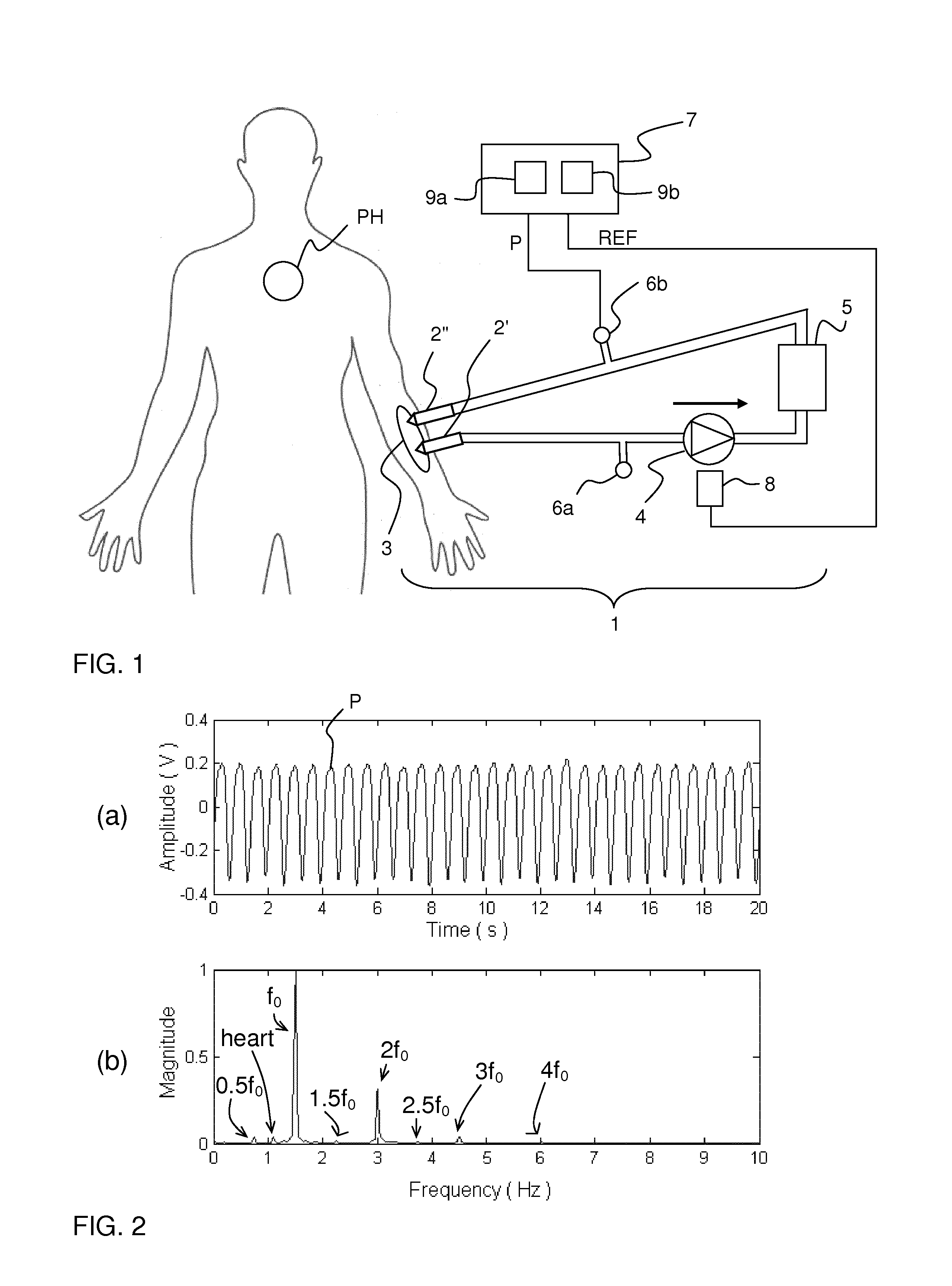
[0128]The speed of the blood pump is typically known beforehand since it is set for the dialysis machine by the clinical staff. However, to make the proposed method independent of the machine settings, the number of pump revolutions in a certain time interval, denoted by Np, is determined from the zero crossings of the observed signal y(t), see FIG. 8(b). If the pump speed for some reason is altered by the staff during treatment, it is straightforward to re-estimate Np. Initially, the pump speed is assumed to be constant with period length Tp, corresponding to one complete revolution of 360 degrees. The onset time of the k:th revolution is given by

tp,k=kTp,k=0,Np−1.  (1)

[0129]For simplicity, the onset time of the first revolution is assumed to be at 0. An initial pump cycle profile p(t;Tp) is obt...


PUM


Abstract

A filtering device receives a signal from a pressure sensor in an extracorporeal fluid circuit connected to a subject and processes the signal to separate physiological pulses, e.g. from the subject's heart, from interference pulses, e.g. from a pump in the fluid circuit. The device repeatedly (iteratively) processes a signal segment by alternately subtracting (S3) a template signal from the signal segment, and applying a refinement processing (S6) to the resulting difference signal to generate a new template signal. By proper selection (S2) of the initial template signal, consecutive difference signals will alternately approximate the sequence of interference pulses in the signal segment and the sequence of physiological pulses in the signal segment. The refinement processing (S6) aims at alternately cleaning up unwanted residuals from interference pulses and physiological pulses, respectively, in the respective difference signal, so as to improve the accuracy of the template signal between the subtractions.

Description

TECHNICAL FIELD[0001]The present invention relates to a technique for processing a pressure signal obtained from a pressure sensor in an extracorporeal fluid circuit, in particular for the purpose of separating interference pulses from physiological pulses in the pressure signal. The interference pulses originate from an interference generator associated with the extracorporeal fluid circuit, and the physiological pulses originate from a physiological pulse generator in a subject connected to the extracorporeal fluid circuit. The present invention is e.g. applicable in connection with extracorporeal blood treatment.BACKGROUND ART[0002]In extracorporeal blood processing, blood is taken out of a human subject, processed (e.g. treated) and then reintroduced into the subject by means of an extracorporeal fluid circuit (“EC circuit”) which is part of a blood processing apparatus. Generally, the blood is circulated through the EC circuit by a blood pump. In certain types of extracorporeal...

Claims


Application Information

Patent Timeline
IPC IPC(8): A61M1/36A61B5/00
CPCA61M1/3656A61M2205/3331A61B5/7235A61B5/7217A61B5/02108A61B5/4836A61M2230/30
Inventor HOLMER, MATTIASOLDE, BOSOLEM, KRISTIANSORNMO, LEIF
Owner GAMBRO LUNDIA AB
Learn More