
Motor controller

a technology of motor controller and motor control, which is applied in the direction of motor/generator/converter stopper, dynamo-electric converter control, polyphase induction motor starter, etc., can solve the problem that the inter-terminal voltage of the smoothing capacitor cannot be sufficiently suppressed, so as to reduce the loss of power converter and reduce the noise of power converter.

Inactive Publication Date: 2016-06-30
TOYOTA JIDOSHA KK
View PDF4 Cites 9 Cited by
  • Summary
  • Abstract
  • Description
  • Claims
  • Application Information

AI Technical Summary

Benefits of technology

The invention is a motor controller that reduces ripples in the voltage of a smoothing capacitor, which helps reduce power conversion loss and noise. The controller achieves this by increasing the frequency of the carrier signal, which has the effect of reducing the power converter's loss.

Problems solved by technology

Nevertheless, depending on the factor that causes the generation of ripples of the inter-terminal voltage of the smoothing capacitor, there is a technical problem in that the ripples of the inter-terminal voltage of the smoothing capacitor cannot be sufficiently suppressed only with the techniques disclosed in JP 2010-263775 A and JP 2004-120853 A.

Method used


Image

  • Motor controller
  • Motor controller
  • Motor controller

Examples


first embodiment

(1) First Embodiment

[0045]The first embodiment is foremost explained with reference to FIGS. 1 to 7.

(1-1) Configuration of Vehicle of First Embodiment

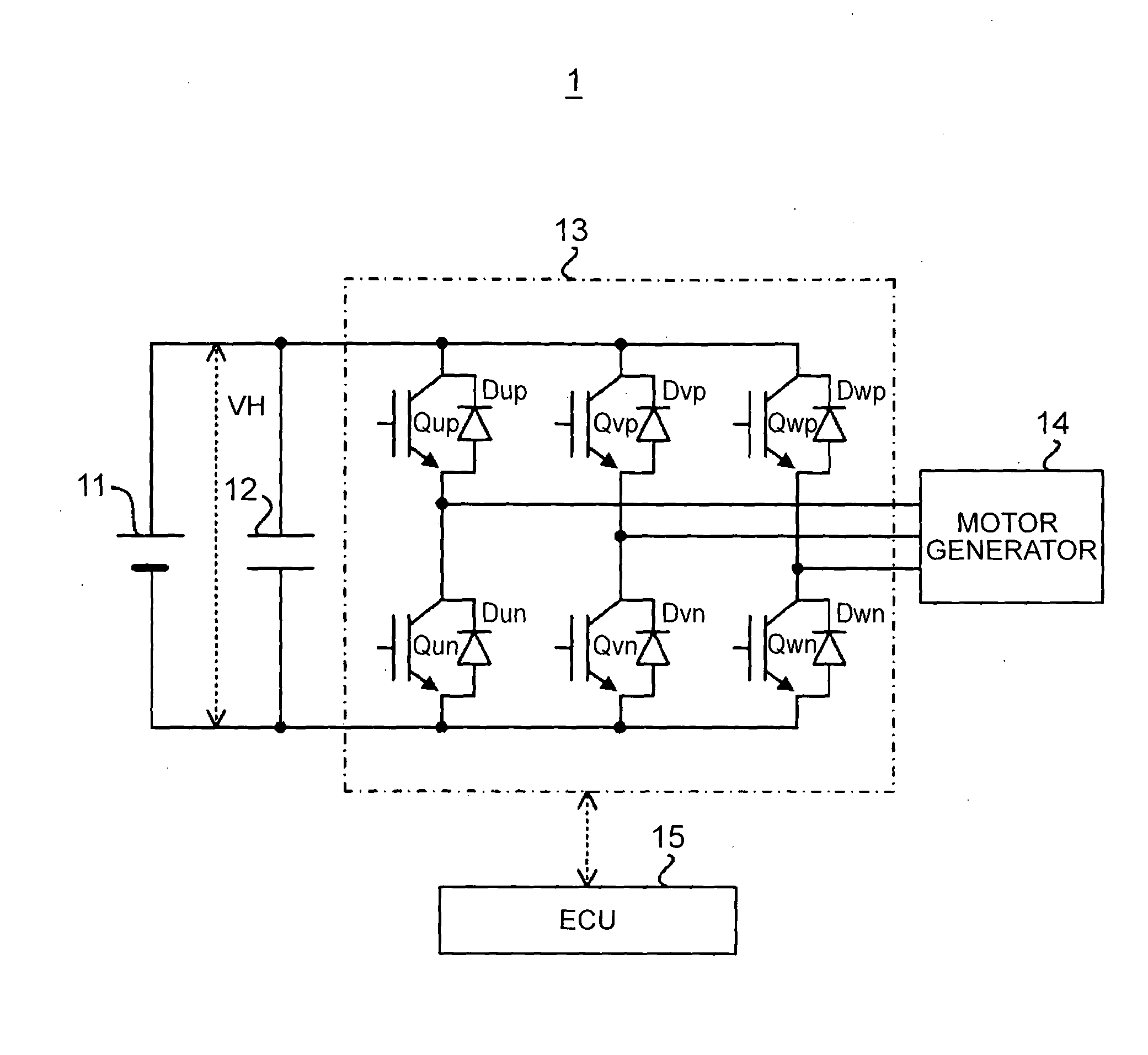
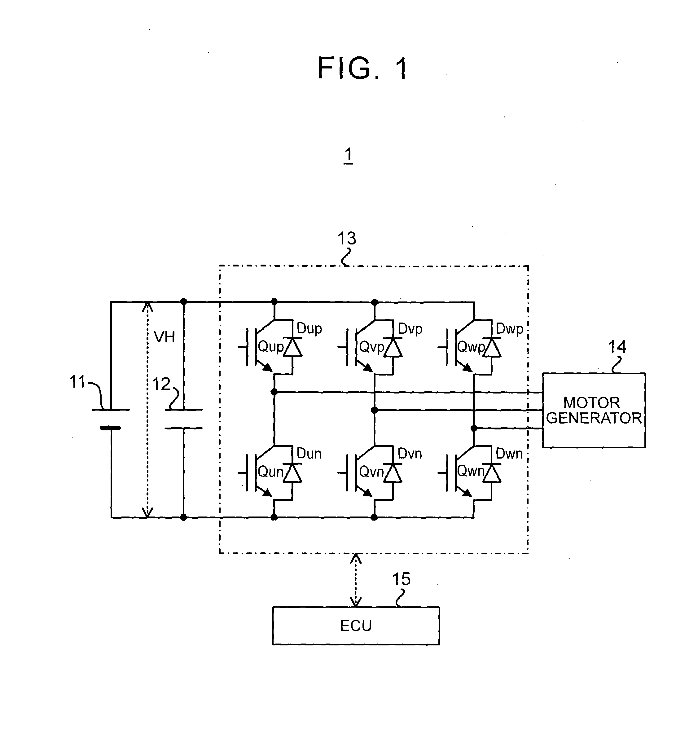
[0046]The configuration of a vehicle 1 of the first embodiment is foremost explained with reference to FIG. 1. FIG. 1 is a block diagram showing the configuration of the vehicle 1 of the first embodiment.

[0047]As shown in FIG. 1, the vehicle 1 includes a DC power supply 11, a smoothing capacitor 12, an inverter 13 as a specific example of a “power converter”, a motor generator 14 as a specific example of a “three-phase AC motor”, and an electronic control unit (ECU) 15 as a specific example of a “motor controller”.

[0048]The DC power supply 11 is a chargeable electrical storage device. As examples of the DC power supply 11, there are, for example, a secondary battery (for instance, nickel-metal hydride battery or lithium-ion battery), and a capacitor (for instance, electric double layer phase capacitor or large-capacity).

[0049]The smoot...

second embodiment

(2) Second Embodiment

[0095]The second embodiment is now explained with reference to FIGS. 8, 9 and 10A to 10C. Note that the same reference number and step number are given to the constituent elements and operation of the vehicle 1 in the first embodiment, and the detailed explanation thereof is omitted.

(2-1) Configuration of Vehicle of Second Embodiment

[0096]The configuration of a vehicle 2 of the second embodiment is foremost explained with reference to FIG. 8. FIG. 8 is a block diagram showing a configuration of the vehicle 2 of the second embodiment.

[0097]As shown in FIG. 8, the vehicle 2 of the second embodiment differs from the vehicle 1 of the first embodiment with respect to the point of including an ECU 25 in substitute for the ECU 15. More specifically, the vehicle 2 of the second embodiment differs from the vehicle 1 of the first embodiment, in which the ECU 15 does not need to be equipped with a frequency adjusting unit 258, with respect to the point that the ECU 25 incl...


PUM


Abstract

Provided is a motor controller for controlling a motor system including a power converter, a smoothing capacitor and a three-phase AC motor. The motor controller includes a generation unit configured to generate a modulation signal by adding a third harmonic signal to a phase voltage command signal, and a control unit configured to control an operation of the power converter using the modulation signal. The third harmonic signal includes a first signal component that causes an absolute value of a signal level of the modulation signal to be greater than an absolute value of a signal level of the phase voltage command signal at a timing in which an absolute value of a signal level of a phase current becomes minimum in each phase

Description

BACKGROUND OF THE INVENTION[0001]1. Field of the Invention[0002]This invention relates to, for example, the technical field of a motor controller configured to control a motor system including a three-phase alternating current (AC) motor.[0003]2. Description of Related Art[0004]As one example of a control method for driving a three-phase AC motor, there is pulse width modulation (PWM) control. PWM control controls a power converter that converts a direct current (DC) voltage (DC power) into an AC voltage (AC power) according to the magnitude relation of a phase voltage command signal, which is set from the perspective of causing a phase current supplied to the three-phase AC motor to coincide with an intended value, and a carrier signal of a predetermined frequency (refer to Japanese Patent Application Publication No. 2004-120853 (JP 2004-120853 A)). Note that PWM control is also used for controlling a power converter that converts an AC voltage into a DC voltage (refer to Japanese ...

Claims


Application Information

Patent Timeline
Patent Type & Authority Applications(United States)
IPC IPC(8): H02P27/08
CPCH02P27/08H02P27/06
Inventor YAMAKAWA, TOSHIFUMIOKAMURA, MASAKITAKAMATSU, NAOYOSHI
Owner TOYOTA JIDOSHA KK
Learn More