
Climate controller

a technology for controlling devices and climate control, applied in lighting and heating apparatus, heating types, instruments, etc., can solve problems such as failure to take into account a user's comfort, problems with this basic ‘dumb’ functionality, and inability to take advantage of modern technology such as machine learning and user experience design

Active Publication Date: 2016-06-30
AMBI LABS
View PDF83 Cites 29 Cited by
  • Summary
  • Abstract
  • Description
  • Claims
  • Application Information

AI Technical Summary

Benefits of technology

The present invention provides a climate controller that can automatically activate and deactivate an HVAC unit based on temperature and humidity measurements. The climate controller uses machine learning methods to optimize energy efficiency by calculating the least energy required to achieve a desired level of comfort. During learning mode, the climate controller cycles the HVAC unit in different modes and measures the temperature and humidity changes. These measurements help to accurately estimate the energy consumption parameters of the HVAC unit and indoor environment. These parameters can then be stored on the climate controller or a networked server for future reference. Overall, the invention allows for efficient climate control that conserves energy while still providing optimal comfort.

Problems solved by technology

Heating, ventilation and air conditioning units (generally referred to as HVAC units) are generally ‘dumb’ devices, not taking advantage of modern technical advances such as machine learning and user experience design.
More advanced HVAC units may control the frequency of their heating or cooling elements via an inverter, meaning that the element does not need to be repeatedly switched on and off, but still fail to take into account a user's comfort.
Problems with this basic ‘dumb’ functionality are immediately apparent.
Cooling the air is not enough—this would increase the relative humidity in the indoor climatic environment, which is why typical HVAC units both cool the air and remove moisture from it.
If humidity is lower, the user's comfort level may be improved but most existing typical HVAC units do not measure humidity.
These factors are not taken into account by the control mechanisms of a typical HVAC unit, which continues its operation regardless, resulting in wasted energy.
When compared to a simple HVAC system which either adds or removes heat from the air based on whether it is on or off, which in turn is based on the absolute temperature, sophisticated control methods may reduce energy consumption but at the risk of increasing the time taken to get to a desired end point apparent temperature.
PCT publication WO2012068517 describes a user friendly, network accessible user interface, but it offers only a relatively dumb interface and does not describe comfort levels or the interaction of temperature, humidity, energy and time.
Significantly, the rules are established in the factory—the patentee knows the exact size of the car, characteristics of the HVAC unit and other inputs that enable this to be effective, but it lacks adaptability.
A further problem with current HVAC infrastructure is that in many buildings, legacy HVAC units are already installed.
The cost of upgrading is high, and some residents may be leaseholders unable or unwilling to replace those HVAC units.
Finally, although modern HVAC units may offer a range of modes which can benefit energy efficiency, a typical user finds this bewildering and has no idea how to set the unit to provide a comfortable environment at the lowest cost—akin to programming a VCR—or even what actually constitutes a comfort level in terms of temperature and humidity.

Method used


Image

  • Climate controller
  • Climate controller
  • Climate controller

Examples


Embodiment Construction

[0038]Mode for Invention

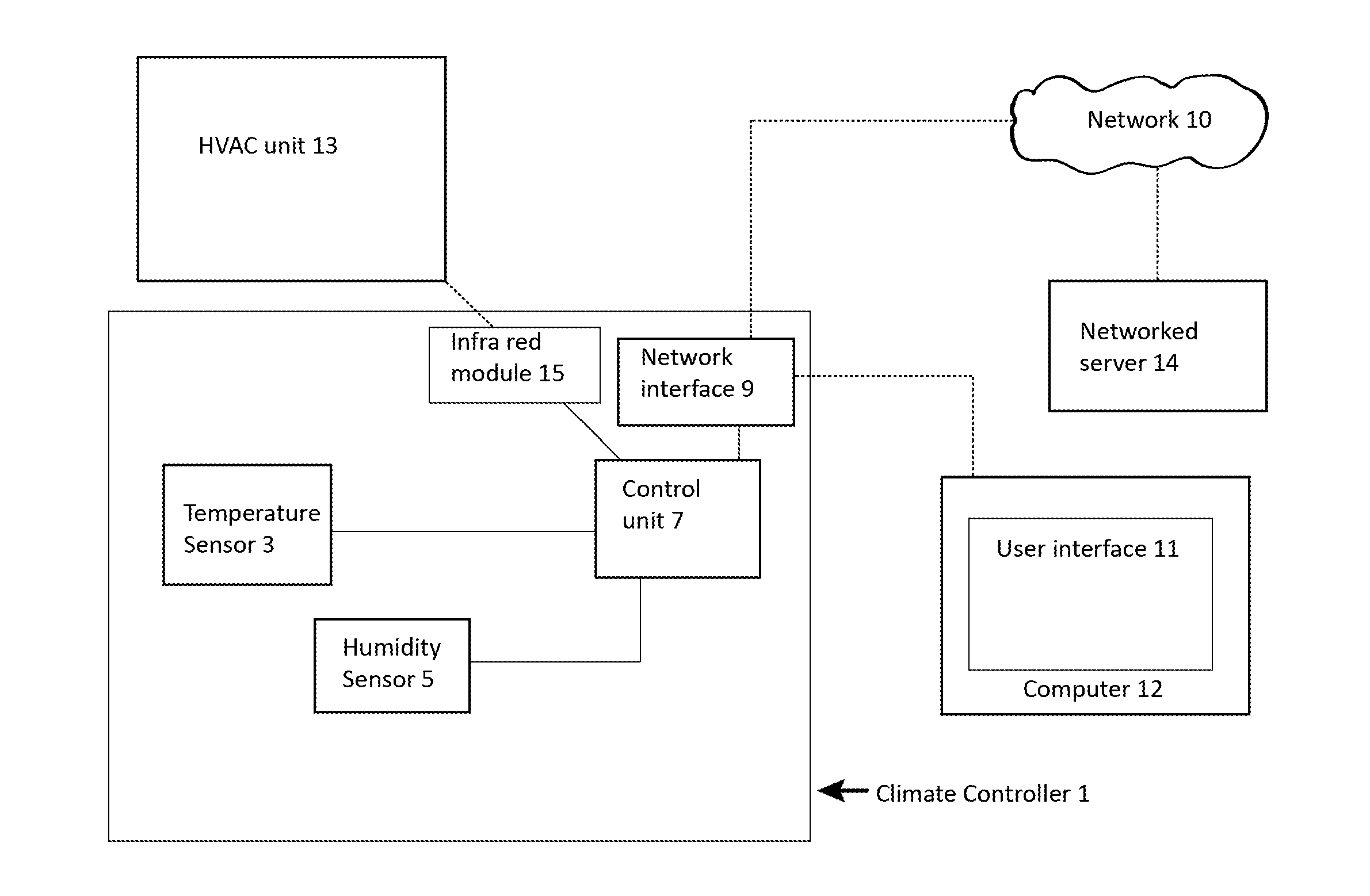
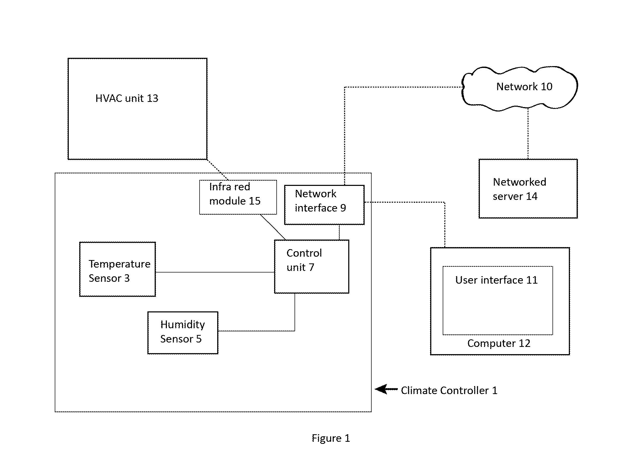
[0039]Referring to the figures, a climate controller 1 comprises a control unit 7 for controlling one or more functions of an HVAC unit 13 servicing a climate controlled space. A temperature sensor 3 takes temperature measurements and communicates the temperature measurements to the control unit 7. A humidity sensor 5 takes humidity measurements and communicates the humidity measurements to the control unit 7. The control unit 7 controls the one or more functions of the HVAC unit 13 based on the temperature and humidity measurements to achieve a desired temperature and a desired humidity in the climate controlled space. The one or more functions can be selected from the following: temperature setting, fan speed setting, mode, heating / cooling / drying / ventilation mode setting, and on / off setting. However, HVAC units can include other functions and these can also be selected.

[0040]The control unit 7 controls the functions of the HVAC unit by sending signals to th...


PUM


Abstract

A climate controller (1), comprises a control unit (7) capable of activating and de-activating an HVAC unit (13), a temperature sensor (3) and a humidity sensor (5) capable of communicating temperature and relative humidity measurements to the control unit (7), and an interface (9) to a network (10) through which the control unit (7) is connected to a networked server (14) and transmits measurements of temperature and relative humidity; said activation and de-activation can be controlled by the control unit (7) which measures a temperature and humidity level, obtains a value for a temperature setting and mode of operation for the HVAC unit (13), and communicates a signal to the HVAC unit (13) to effect said activation and de-activation. Climate control is affected with a comfort level in preference to an absolute temperature, and energy efficiency is achieved by machine learning methods operated on data sets gathered by the climate controller (1).

Description

TECHNICAL FIELD[0001]The invention relates to indoor climate control and more particularly to controllers and methods for the control of indoor climate control appliances. The invention has been described herein primarily in relation to controlling HVAC units, but is not limited to this particular application. CL BACKGROUND ART[0002]Heating, ventilation and air conditioning units (generally referred to as HVAC units) are generally ‘dumb’ devices, not taking advantage of modern technical advances such as machine learning and user experience design. A user of a typical HVAC unit is presented with a number of modes, such as heating, cooling, drying (removal of moisture from the air), fan and off, and a desired indoor room temperature. The user selects his preferred mode, sets the desired temperature, and the HVAC unit will run its heating or cooling element until that temperature is reached, then switch it off, then when there is a temperature differential again it will switch it on ag...

Claims


Application Information

Patent Timeline
IPC IPC(8): G05D27/02G05D23/19F24F11/00G05D22/02
CPCG05D27/02G05D22/02G05D23/19F24F2011/0075F24F11/006F24F2011/0063F24F2011/0068F24F11/0008G05D23/1902F24F11/30F24F2110/10F24F2110/20F24F11/62F24F11/64F24F11/56F24F11/46F24F11/77F24F11/58F24F11/523F24F11/65
Inventor LEE, JULIANANTONY, MATHIS
Owner AMBI LABS
Learn More