Liquid discharging apparatus, head unit, capacitive load driving circuit, and integrated circuit device for capacitive load driving

a capacitive load and liquid discharging technology, applied in the direction of oscillator generators, pulse techniques, printing, etc., can solve the problems of affecting the quality of printing, the influence of various types of noise, and the effect of increasing switching loss and noise prevention

Active Publication Date: 2016-06-16
SEIKO EPSON CORP
View PDF2 Cites 1 Cited by
  • Summary
  • Abstract
  • Description
  • Claims
  • Application Information

AI Technical Summary

Benefits of technology

The invention is about a liquid discharging apparatus and its components. The technical effect of this invention is to improve the accuracy of liquid discharge. This is achieved by disposing a ground terminal close to the feedback terminal, which prevents noise from affecting the feedback signal. This results in a modulation signal with high accuracy, allowing for better control of the voltage applied to the piezoelectric element, and ultimately improving the discharge accuracy of liquid.

Problems solved by technology

However, due to the high oscillation frequency, the influence of various types of noise is likely to occur.
When the waveform of the driving signal is blunt, the displacement of the piezoelectric element which is operated in accordance with a rising or falling edge of the waveform becomes slow, tailing during discharge or a discharge defect is generated, and the quality of printing deteriorates.
However, as switching frequency increases in the transistor, switching loss increases, and compared to linear amplification of a class-AB amplifier or the like, excellent power saving performance and generated heat saving performance are deteriorated.

Method used


Image

  • Liquid discharging apparatus, head unit, capacitive load driving circuit, and integrated circuit device for capacitive load driving
  • Liquid discharging apparatus, head unit, capacitive load driving circuit, and integrated circuit device for capacitive load driving
  • Liquid discharging apparatus, head unit, capacitive load driving circuit, and integrated circuit device for capacitive load driving

Examples


Embodiment Construction

[0047]Hereinafter, an appropriate embodiment of the invention will be described in detail by using the drawings. The drawings used are for convenience of the description. In addition, the embodiment which will be described hereinafter does not inappropriately limit the contents of the invention described within the range of the patent claims. All of the configurations which will be described hereinafter are not necessarily essential configuration requirements of the invention.

1. Outline of Liquid Discharging Apparatus

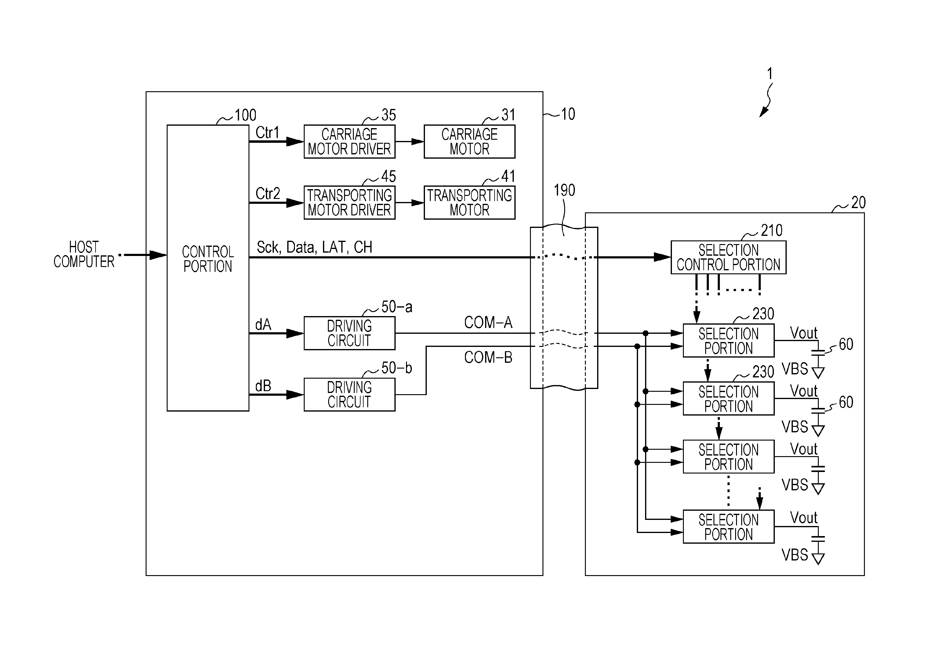
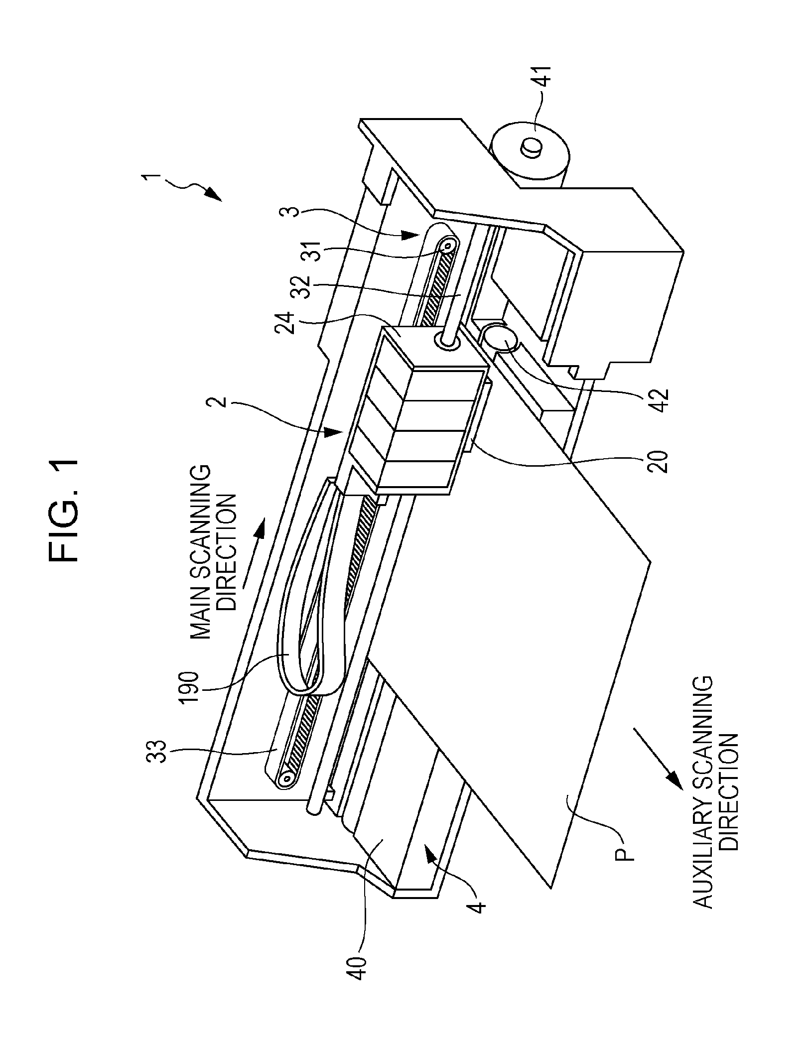
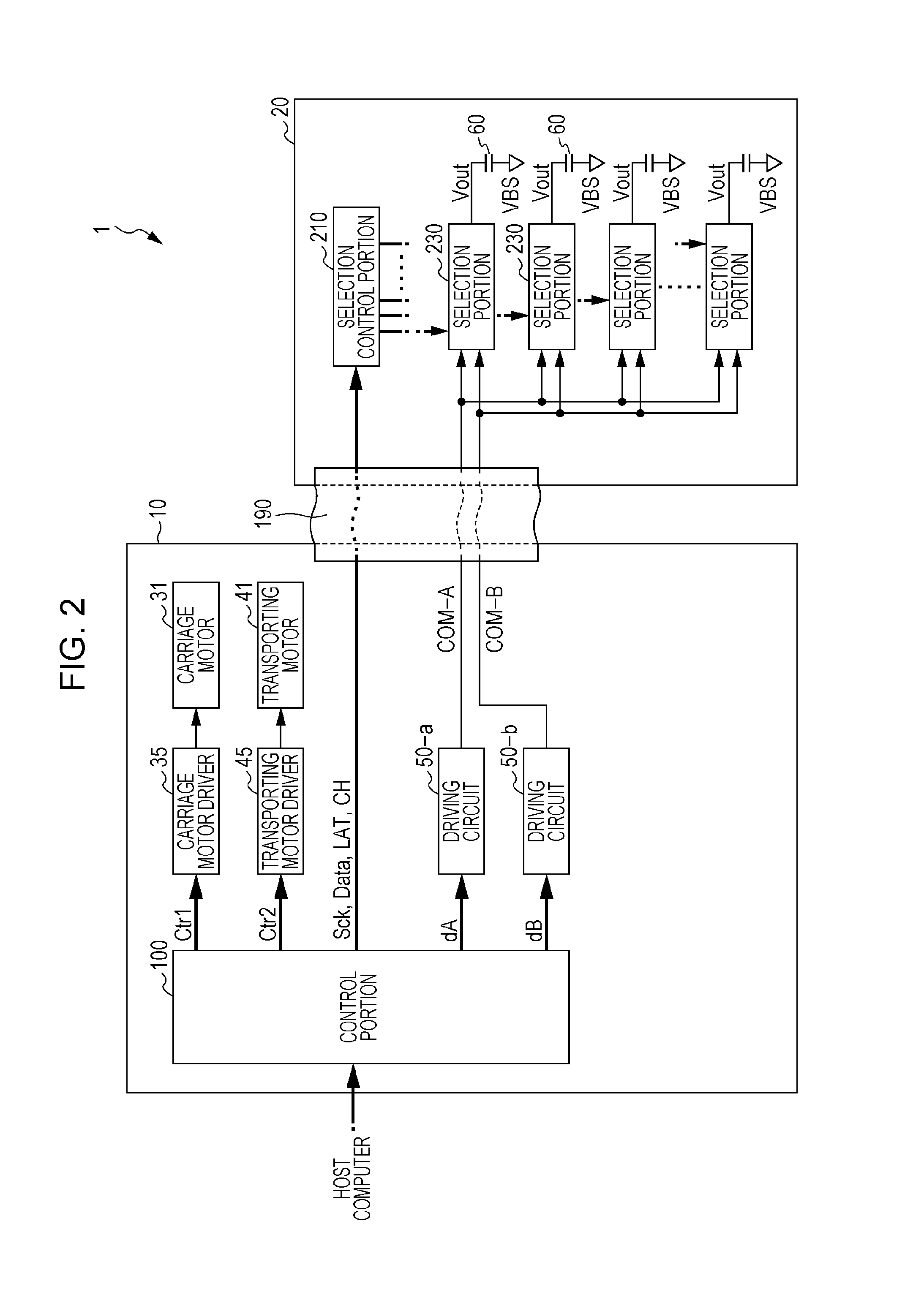
[0048]A printing apparatus which is an example of a liquid discharging apparatus according to the embodiment is an ink jet printer which forms an ink dot group on a printing medium, such as a paper sheet by discharging ink in accordance with image data supplied from an external host computer, and accordingly, prints an image (including characters or figures) which corresponds to the image data.

[0049]Examples of the liquid discharging apparatus include a printing apparat...


PUM


Abstract

There is provided a liquid discharging apparatus including: a modulation portion which generates a modulation signal pulse-modulated from a source signal; a ground terminal which electrically connects the modulation portion to a ground potential; a transistor which generates an amplification modulation signal amplified from the modulation signal; a low pass filter which demodulates the amplification modulation signal and generates a driving signal; a feedback circuit which generates a feedback signal based on the driving signal, and sends back the feedback signal to the modulation portion via a feedback terminal; and a piezoelectric element which is displaced as the driving signal is applied, in which the modulation portion, the ground terminal, and the feedback terminal are formed on the same semiconductor substrate, and in which, in a plan view, the ground terminal and the feedback terminal are disposed being adjacent to each other.

Description

[0001]The entire disclosure of Japanese Patent Application No. 2014-249950, filed Dec. 10, 2014 is expressly incorporated by reference herein.BACKGROUND[0002]1. Technical Field[0003]The present invention relates to a liquid discharging apparatus, a head unit, a capacitive load driving circuit, and an integrated circuit device for capacitive load driving.[0004]2. Related Art[0005]In a liquid discharging apparatus, such as an ink jet printer, which discharges ink and prints an image or a document, an apparatus which uses a piezoelectric element (for example, a piezo element) has been known. The piezoelectric elements are provided corresponding to each of a plurality of nozzles in a head unit, and each of the piezoelectric elements is driven in accordance with driving signals. Accordingly, a predetermined amount of ink (liquid) is discharged from the nozzle at a predetermined timing, and a dot is formed. Since the piezoelectric element is a capacitive load, such as a capacitor, in term...

Claims


Application Information

Patent Timeline
IPC IPC(8): B41J2/045
CPCB41J2/04581B41J2/04541B41J2/0451B41J2/14233B41J2002/14491
Inventor FUJITA, TADAHIRO
Owner SEIKO EPSON CORP
Why Eureka
Try Eureka