Image display device, correction data generation method, and image correction device and method, as well as image correction system

Inactive Publication Date: 2016-06-09
MEGACHIPS
View PDF5 Cites 6 Cited by
  • Summary
  • Abstract
  • Description
  • Claims
  • Application Information

AI Technical Summary

Benefits of technology

This patent aims to solve the problem of requiring large amounts of correction to mitigate brightness unevenness in images, which leads to increased takt time and decreased production efficiency. The invention proposes a method to generate correction data by using a pattern image obtained by combining a flat pattern image and a vignetting pattern image. This method reduces the amount of correction needed and enables sufficient correction accuracy to be achieved with just one image capture, resulting in a faster takt time and improved production efficiency.

Problems solved by technology

When the amounts of correction are large, imaging the image one time is not enough to attain sufficient correction accuracy and the image needs to be repeatedly imaged two or three times to finish the generation of correction data.
However, repetitive imaging of the image leads to increased takt time and lower production efficiency.

Method used


Image

  • Image display device, correction data generation method, and image correction device and method, as well as image correction system
  • Image display device, correction data generation method, and image correction device and method, as well as image correction system
  • Image display device, correction data generation method, and image correction device and method, as well as image correction system

Examples


Embodiment Construction

[0047]On the following pages, an image display device, correction data generation method and an image correction device and method as well as an image correction system of the invention are described in detail with reference to preferred embodiments shown in the accompanying drawings.

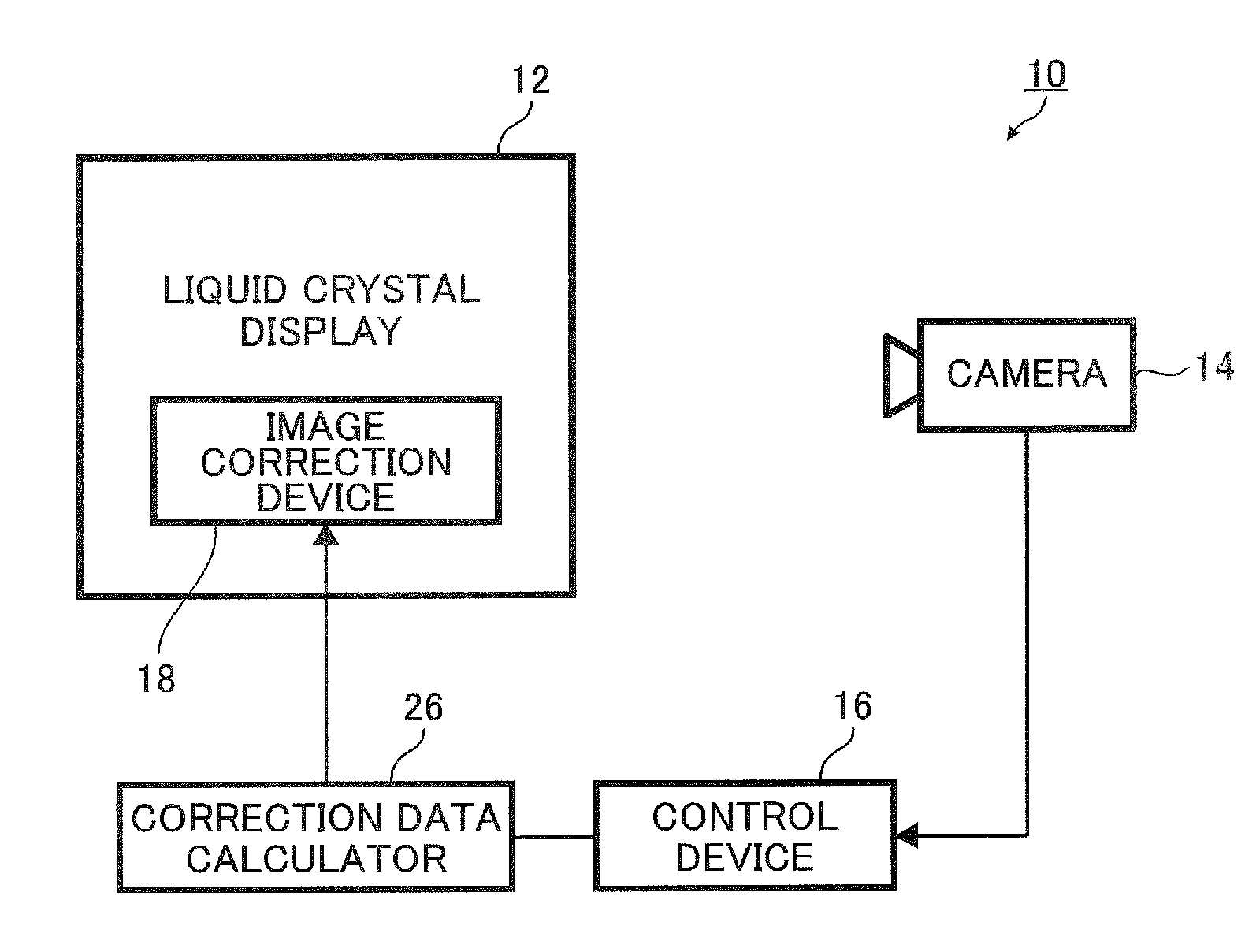
[0048]FIG. 1 is a conceptual diagram of an embodiment for showing the configuration of an image correction system of the invention. An image correction system 10 shown in FIG. 1 serves to generate correction data for correcting brightness unevenness of an input image inputted to a liquid crystal display 12 and correct the brightness unevenness of the input image using the generated correction data, and is constituted of a camera 14, a control device 16, a correction data calculator 26 and an image correction device 18.

[0049]The camera 14 images a pattern image displayed on the liquid crystal display 12 to generate image data of the captured image.

[0050]The camera 14 may be used to manually image a patte...


PUM


Abstract

In the image display device, the vignetting pattern generator generates a vignetting pattern image composed of image data having inverted brightness characteristics obtained by inverting brightness characteristics of a panel of the liquid crystal display. The display controller carries out control to cause a pattern image obtained by combining a flat pattern image in gray composed of image data having a uniform grayscale level and the vignetting pattern image to be displayed on the liquid crystal display. And the correction data calculator calculates correction data for correcting brightness unevenness of an input image based on brightness values of image data of captured images obtained by imaging, by the camera, the pattern images displayed on the liquid crystal display.

Description

CROSS-REFERENCE TO RELATED APPLICATIONS[0001]The present application claims priority under 35 U.S.C. §119 to Japanese Patent Application No. 2014-249238, filed on Dec. 9, 2014. The above application is hereby expressly incorporated by reference, in its entirety, into the present application.BACKGROUND OF THE INVENTION[0002]The present invention relates to an image display device that causes an image used for generating correction data for correcting brightness unevenness of an input image inputted to a liquid crystal display to be displayed on the liquid crystal display, a correction data generation method for generating the correction data, and an image correction device and method for correcting brightness unevenness of an input image with the correction data, as well as an image correction system.[0003]Occasionally, liquid crystal displays do not exhibit uniform brightness and brightness unevenness may occur. Occurrence of brightness unevenness means significant degradation in di...

Claims


Application Information

Patent Timeline
IPC IPC(8): G09G3/20G09G3/36
CPCG09G3/2007G09G3/36G09G2320/029G09G2320/0271G09G2320/0233
Inventor SUGIYAMA, HITOSHINAKANO, HIDEOKOMINE, JUNICHI
Owner MEGACHIPS
Why Eureka
Try Eureka