Robot system

A robot system and robot technology, applied in the field of robot systems, can solve the problems of longer production takt time, rising air conditioning costs, and larger workshop itself, and achieve the effect of shortening production takt time, reducing air conditioning costs, and shrinking the workshop itself.

Inactive Publication Date: 2013-03-20
YASKAWA DENKI KK
View PDF2 Cites 0 Cited by
  • Summary
  • Abstract
  • Description
  • Claims
  • Application Information

AI Technical Summary

Problems solved by technology

[0009] In the existing robot system, although a production line is constructed in which a robot and a positioner are used to weld objects to be worked, and to sequentially hand over objects to be worked between work processes, since the positioner is arranged in the work area of ​​the robot Therefore, the space for installing the positioner and the space for installing the robot are required separately, and there is a problem of increasing the corresponding amount of the working space, and there are problems of increasing the workshop space and increasing the cost of the air conditioner.
[0010] In addition, in the case of welding a long piece, in the production line shown in Patent Document 2, the welding robot, the transfer robot, and the positioner become longer in the advancing direction of the production line, and are also configured to be longer in the next process. production line, so there is a tendency for continuous production lines to become longer
In this way, since a long production line is formed, the floor space becomes larger, and there is a problem that the workshop itself becomes larger.
In addition, since the distance between processes becomes longer, the tact time becomes longer, resulting in a problem that manufacturing time is consumed

Method used


Image

  • Robot system
  • Robot system
  • Robot system

Examples


Embodiment 1

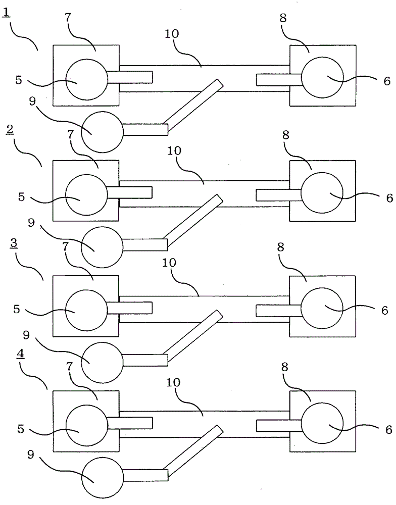
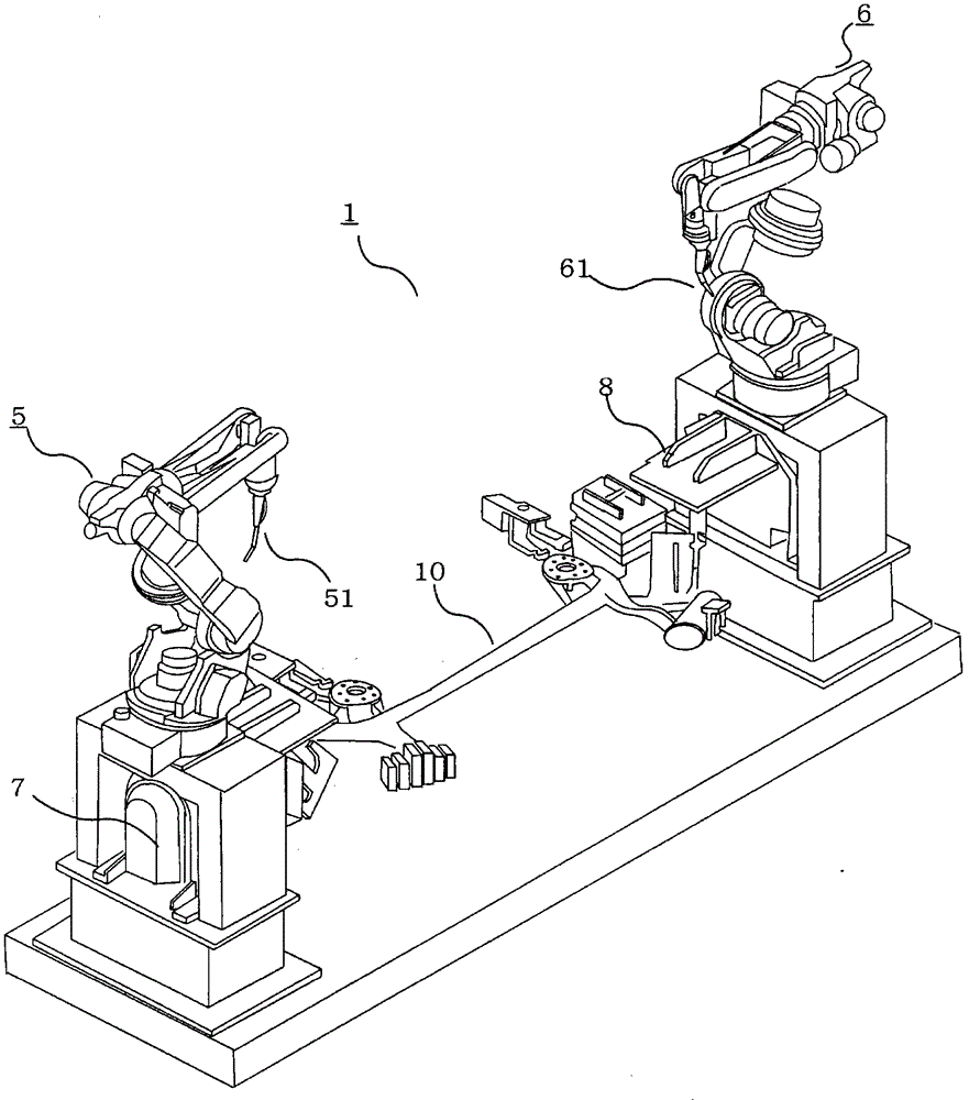
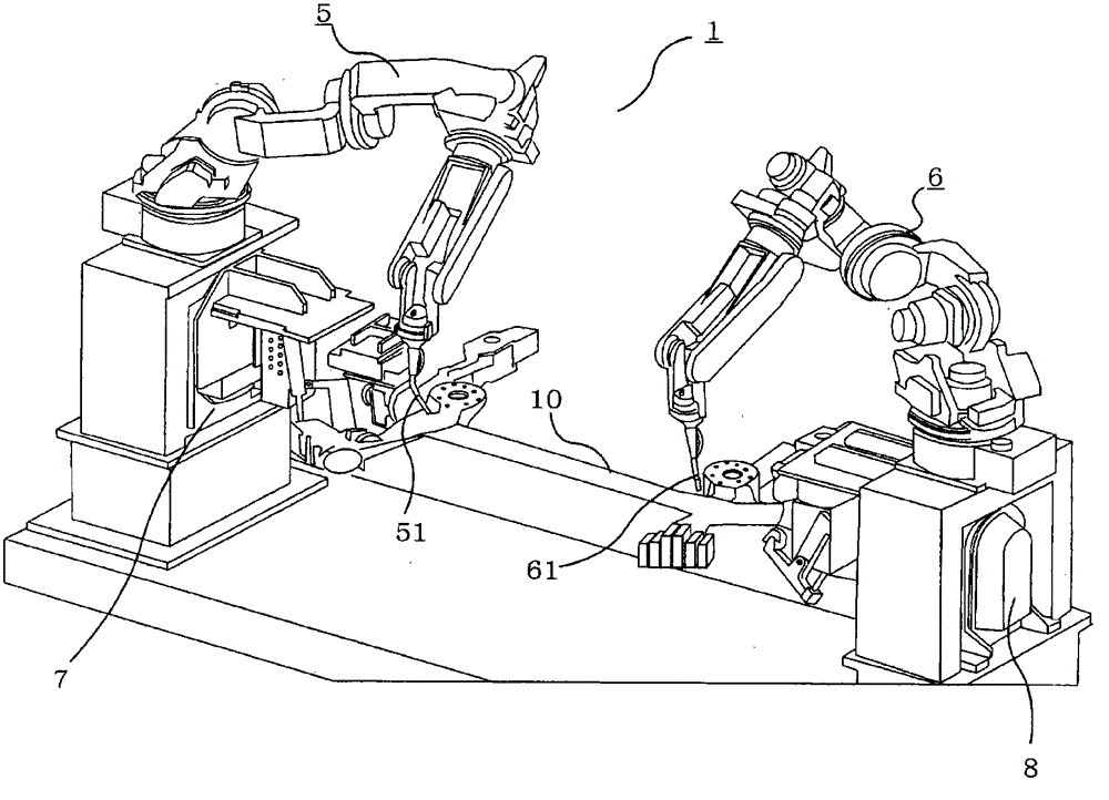
[0033] figure 1 is a plan view of the robot system of the present invention. Number 1 is the first welding process, number 2 is the second welding process, number 3 is the third welding process, number 4 is the fourth welding process, number 5 is the first welding robot, number 6 is the second welding robot, number 7 is the first positioner, the number 8 is the second positioner, the number 9 is the transfer robot, and the number 10 is the work object.

[0034] The difference between the present invention and the prior art lies in that an industrial robot is installed on a positioner and performs work on a work object.

[0035] The work object 10 is, for example, a long piece such as a chassis of a motor vehicle, and the work object 10 is attached to the first positioner 7 and the second positioner 8 in the first welding process by a transfer robot (not shown). Next, the first positioner 7 and the second positioner 8 rotate to align the welding position, and then the first w...


PUM

PropertyMeasurementUnit
degree of freedomaaaaaaaaaa

Abstract

The present invention provides a robot system in which a robot and a positioner are combined with each other. In the robot system, footprint is reduced and a production line having a short tact time between steps is formed. A robot system includes a work object (10), robots (5), (6) that perform a work operation on the work object (10), and positioners (7), (8) that position the work object (10), wherein the robots (5), (6) are provided on frame members of the positioners (7), (8).

Description

technical field [0001] The present invention relates to a robot system using a vertical articulated robot. Background technique [0002] In a production line using industrial robots in recent years, there is a tendency to arrange robots densely to compress the manufacturing process. That is, the footprint of the robot is reduced, and the workshop itself is reduced in size, thereby suppressing costs required for air conditioning in the workshop and reducing air conditioning equipment. In addition, tact time can be shortened by shortening the distance between work steps, so it is desired to tighten the manufacturing process. [0003] A typical example of a production line equipped with such a manufacturing process is a welding line for automotive parts. As a conventional welding line system, a system using a positioner (positioner) for positioning a robot and parts has been proposed (for example, refer to Patent Document 1). The structure of this system is an example of a p...

Claims


Application Information

Patent Timeline
Patent Type & Authority Patents(China)
IPC IPC(8): B25J19/00B23K9/12
CPCB23K2201/006B23K37/047Y10S269/903B23K31/02B23K9/02B23K37/0426B25J9/0084B23K2101/006
Inventor 西川清吾白木知行广田博康松尾智弘
Owner YASKAWA DENKI KK
Why Eureka
Try Eureka