Suction device of engine

An air suction device and engine technology, which is applied to engine components, combustion engines, machines/engines, etc., can solve the problems of difficulty in protecting the casing and large configuration space for the air suction system, and achieve the effect of simple installation work and omitting installation space.

Inactive Publication Date: 2014-04-09
HONDA MOTOR CO LTD
View PDF7 Cites 0 Cited by
  • Summary
  • Abstract
  • Description
  • Claims
  • Application Information

AI Technical Summary

Problems solved by technology

[0008] However, the target vehicle of the above-mentioned patent document is a four-wheel vehicle, which has a relatively large space for the arrangement of the air intake system.
[0009] However, in a small vehicle such as a saddled vehicle, there is a big problem in ensuring a sufficient length of the intake pipe, and furthermore, an installation space for a drive source for switching the air flow path.
[0010] Furthermore, in the case of providing a drive source for switching the air flow path, in order to ensure that the drive source works well for a long period of time, it is desirable to provide a structure such as a housing protection case for protection, but the current situation is to provide such a protection case Solid structure is difficult to install in a space-saving manner

Method used


Image

  • Suction device of engine
  • Suction device of engine
  • Suction device of engine

Examples


Embodiment Construction

[0066] Hereinafter, an embodiment of the present invention will be described with reference to the drawings. It should be noted that the drawings are drawings viewed in the direction of the symbols, and Fr, Rr, U, D, R, and L shown in the drawings represent the front, rear, upper, lower, right, left.

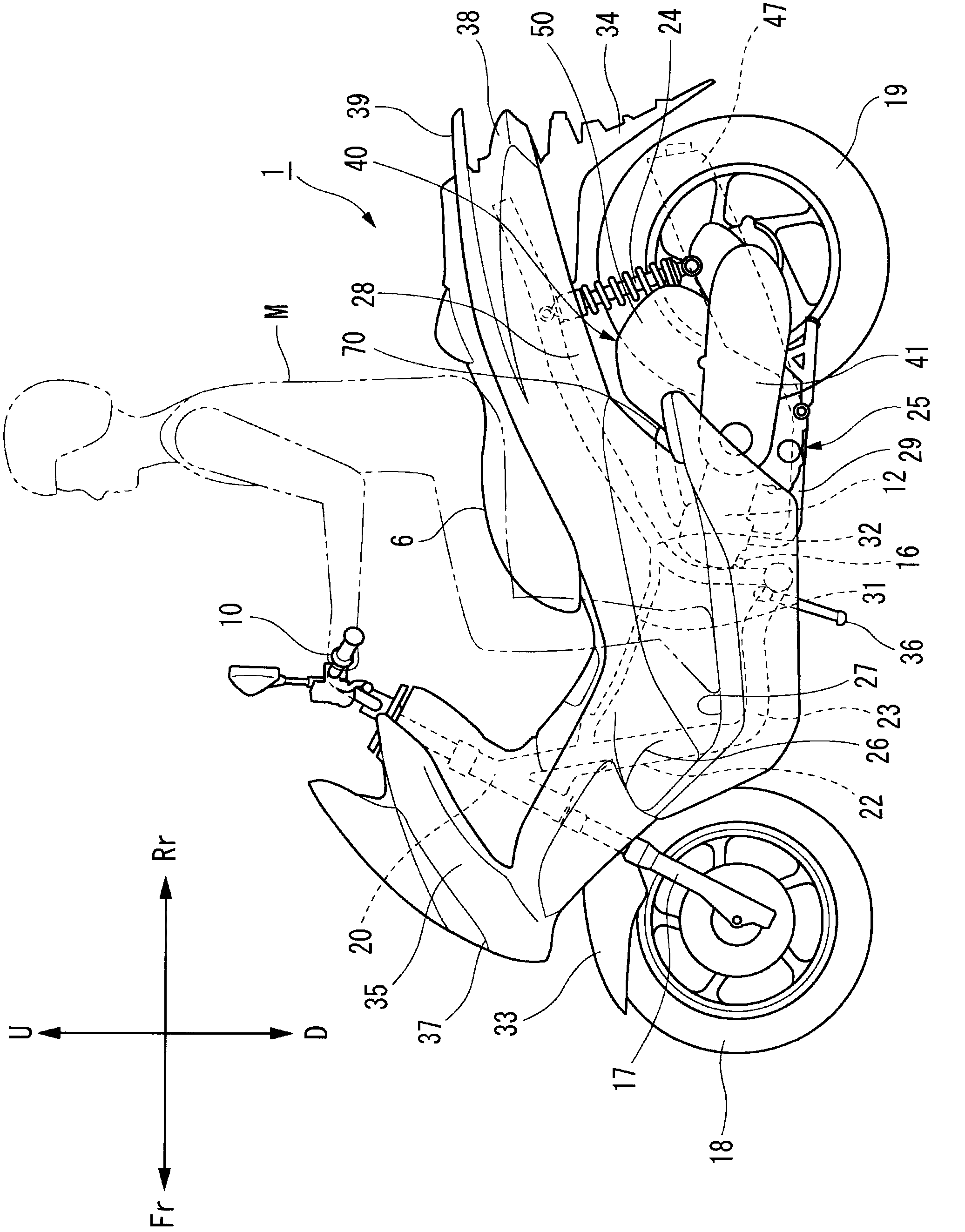
[0067] figure 1 It is a left side view of the low-floor straddle vehicle according to the embodiment of the present invention.

[0068] In the low-floor straddle-type two-wheeled vehicle 1 which is a low-floor straddle type vehicle, the vehicle frame is constituted by a front frame 31 and a rear frame 32 (seat rail) as a seat rail, etc., wherein the The front frame 31 extends rearward and slightly downward from the middle section of the down tube 22, which extends obliquely downward from the head tube 20, and the rear frame 32 extends obliquely upward from the rear end of the bottom tube 23 (in the drawing). The bottom pipe 23 extends horizontally from the lower end of the do...


PUM


Abstract

PROBLEM TO BE SOLVED: To provide a suction device of an engine capable of securing a sufficient length of a suction pipe when applied to a small-sized vehicle, also securing an installation space for a driving source for changing over the air passage, and having a case structure for accommodation and protection to protect the driving source.SOLUTION: The suction device 40 of the engine is formed so that the route of the suction passage can be changed over when the intake is purified by an air cleaner 53 and the mixture gas is supplied to the suction port 12b of the engine 12. A part of the suction pipe 70 leading to the suction port 12b of the engine 12 is arranged inside an air cleaner case 50, and the suction pipe 70 is furnished with a branch passage 76 where a plurality of openings 73 and 74 can be formed in the air cleaner case, and an opening / closing drive device 60 to open and close either of the openings 73 and 74 is installed in the air cleaner case 50.

Description

technical field [0001] The present invention relates to an engine air intake device, and more particularly to an engine air intake device for a straddle-type vehicle which is a small vehicle. Background technique [0002] As for conventional engine air intake devices, for example, an air intake device for a four-cycle multi-cylinder engine of an automobile employs a method of inertial supercharging that increases the amount of intake air by utilizing the motion effect of the intake air column. In this way, the inertial supercharging effect is obtained over the low-speed operation region to the high-speed operation region of the engine. [0003] Therefore, conventionally, an air intake device has been used that increases the effective intake pipe length at low speeds and shortens the effective intake pipe length at high speeds, thereby changing the effective intake pipe length between the low-speed operation range and the high-speed operation range. [0004] As such an air i...

Claims


Application Information

Patent Timeline
Patent Type & Authority Patents(China)
IPC IPC(8): F02B27/02F02M35/10F02M35/02F02M35/16
CPCY02T10/146Y02T10/12
Inventor 与语丰幸堀内哲沼崎芳美
Owner HONDA MOTOR CO LTD
Why Eureka
Try Eureka