
Method and optical device for microscopically examining a multiplicity of specimens

Active Publication Date: 2016-06-02
LEICA MICROSYSTEMS CMS GMBH
View PDF3 Cites 19 Cited by
  • Summary
  • Abstract
  • Description
  • Claims
  • Application Information

AI Technical Summary

Benefits of technology

The invention is a method that lets us inspect multiple samples quickly and easily, without damaging them. This method can be done automatically, making it more efficient and precise. Its technical effects are that it allows for quick and accurate inspection of multiple samples with low impact, and it can be done automatically.

Problems solved by technology

Such a solution is not only very complex but also has the disadvantage that three-dimensional imaging of a plurality of samples would still take a very long time; this is not acceptable in particular with usually lifetime-limited, light-sensitive samples.
Many samples to be investigated microscopically have a limited lifetime.
Three-dimensional scanning, for example using a scanning microscope, of samples arranged, for example, in the form of a matrix on a specimen slide is in this regard problematic in practice, since the scanning operation requires a great deal of time, and sample regions that lie outside the currently relevant scanning point are also respectively impinged upon by illumination light during the scanning operation and thereby damaged.
An entirely different technology, in which the sample is illuminated in layers, in principle allows more rapid acquisition of image data with less impact on samples, but hitherto has not been suitable for rapid mass investigations of samples, because the optical apparatuses required are technically very complex and because the samples must be separately and individually arranged in particular apparatuses and the observation apparatus must be laboriously configured individually for each sample.
In particular, this method as a rule cannot be implemented using apparatuses that have a conventional microscope structure with a standard microscope stand.
Complex and expensive special arrangements are instead needed in order to implement these techniques.
With this embodiment, positioning the sample inside the annular reflector is particularly problematic.
An apparatus of this kind is therefore unsuitable for utilization of an automated method for serial investigation of a plurality of samples.
A procedure of this kind is unsuitable for structured, systematic, and targeted microscopic investigation of a plurality of samples.

Method used


Image

  • Method and optical device for microscopically examining a multiplicity of specimens
  • Method and optical device for microscopically examining a multiplicity of specimens
  • Method and optical device for microscopically examining a multiplicity of specimens

Examples


Embodiment Construction

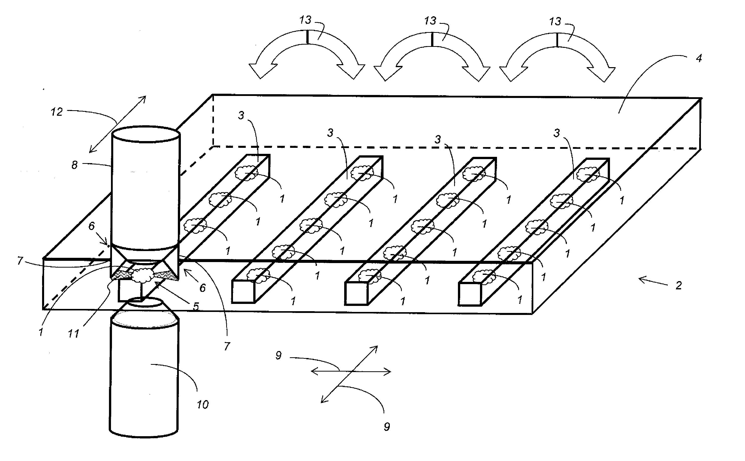
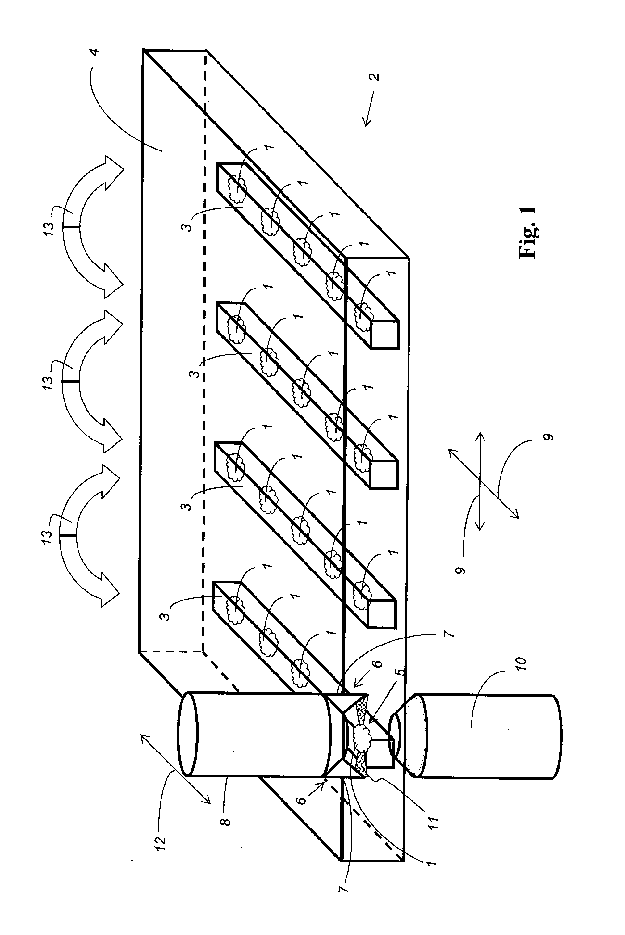
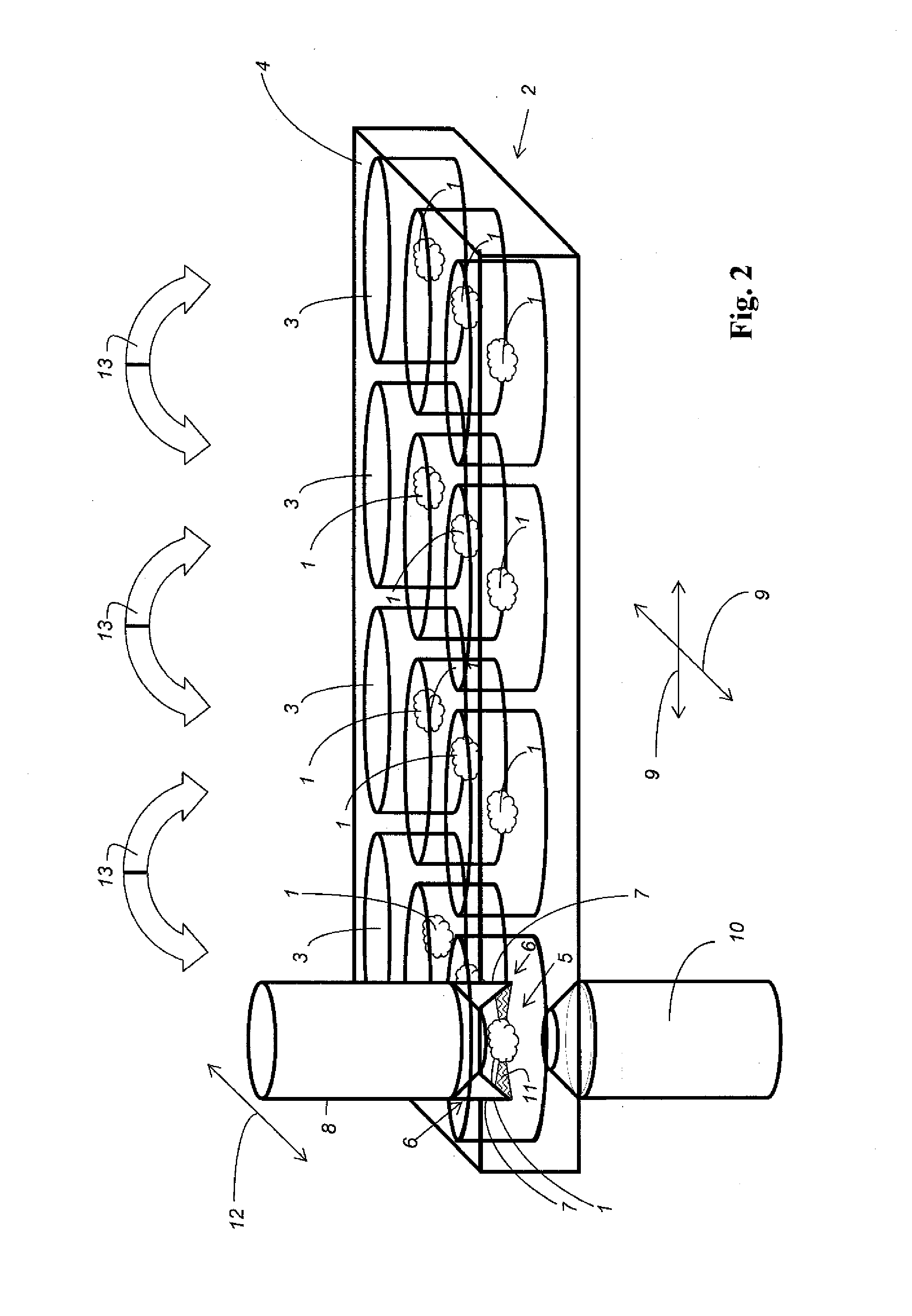
[0069]FIG. 1 is a detail view of an exemplifying embodiment of an optical apparatus according to the present invention for microscopic investigation of a plurality of samples 1, to explain a possible embodiment of the method according to the present invention.

[0070]The optical apparatus comprises a sample holder 2, samples 1 to be investigated being retained in multiple sub-holders 3 of sample holder 2. Sub-holders 3 are each embodied as a strand-shaped cuboid. Each sub-holder 3 is made up of a dimensionally stable embedding medium, for example agarose, or of a (preferably similar) gel-like transparent medium, into which samples 1 held by the respective sub-holder 3 are embedded. Sub-holders 3 are arranged in a common, preferably horizontal plane, and parallel to one another, in a transparent dish 4 of sample holder 2, which dish is filled with an immersion liquid (not depicted). As a result of this special embodiment of sample holder 2 and the special arrangement of samples 1 that ...


PUM


Abstract

The invention relates to a method for microscopic investigation of a plurality of samples. The method contains the step of arranging the samples in a sample holder that is movable, in particular in motorized and / or automatic fashion, relative to a sample illumination position in such a way that at least one of the samples is respectively successively positionable in the sample illumination position, a clearance for a deflection means respectively remaining adjacent to the sample that is currently located in the sample illumination position; the step of focusing a light stripe with an illumination objective; the step of deflecting the light stripe, once it has passed through the illumination objective, with the deflection means in such a way that the light stripe propagates at an angle different from zero degrees with respect to the optical axis of the illumination objective and has a focus in the sample illumination position; and the step of successively positioning the samples, retained with the sample holder, in the sample illumination position, and detecting the detected light emerging from the sample respectively located in the sample illumination position. The invention furthermore relates to an optical apparatus having a sample holder that holds a plurality of samples and is supported movably, in particular in motorized and / or automatic fashion, relative to a sample illumination position in such a way that at least one of the samples is respectively successively positionable in the sample illumination position.

Description

CROSS-REFERENCE TO RELATED APPLICATIONS[0001]The present application is the U.S. national phase of International Application No. PCT / EP2014 / 062907 filed Jun. 18, 2014, which claims priority of German Application No. 10 2013 211 426.5 filed Jun. 18, 2013, the entirety of which is incorporated herein by reference.FIELD OF THE INVENTION[0002]The invention relates to a method for microscopic investigation of a plurality of samples.BACKGROUND OF THE INVENTION[0003]The invention furthermore relates to an optical apparatus for microscopic investigation of a plurality of samples, having a sample holder that holds a plurality of samples and is supported movably, in particular in motorized and / or automatic fashion, relative to a sample illumination position in such a way that at least one of the samples is respectively successively positionable in the sample illumination position.[0004]The need exists in some applications, for example for particular serial investigations or statistical invest...

Claims


Application Information

Patent Timeline
IPC IPC(8): G01N21/13G02B21/26G02B21/00G02B21/06
CPCG01N21/13G02B21/06G01N2021/135G02B21/0024G02B21/26G02B21/0032G02B21/0076G02B21/34G02B21/367
Inventor KNEBEL, WERNERFOUQUET, WERNHERSIECKMANN, FRANK
Owner LEICA MICROSYSTEMS CMS GMBH
Learn More