Eureka AIR delivers breakthrough ideas for toughest innovation challenges, trusted by R&D personnel around the world.

Package Receiving Device

Pending Publication Date: 2022-05-19
GATKE PAUL
View PDF28 Cites 0 Cited by
  • Summary
  • Abstract
  • Description
  • Claims
  • Application Information

AI Technical Summary

Benefits of technology

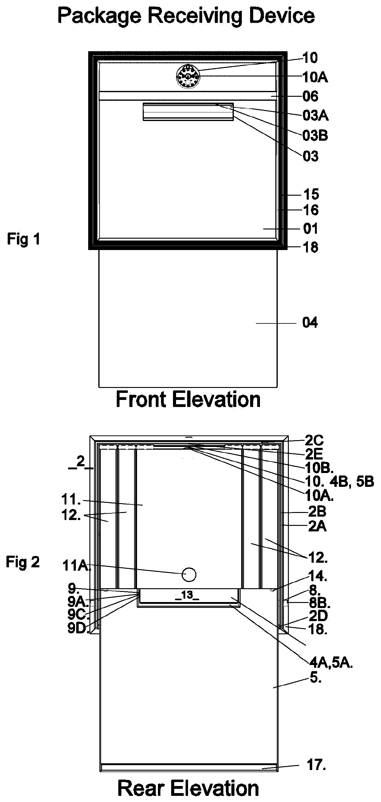
The patent describes a package receiving device that has adjustable hydraulic struts to keep the panel unit in a safe position for people, pets, and packages. There are also vertical swinging slats that can open or close to control the speed and safety of the device. The slats use hinges and are made of metal, Plexiglas, or other composite materials. The device also has aMailbox Assembly with a clear Plexiglas front panel and a package stop to prevent the package from moving too fast to the floor. The device is designed to look like an architectural element and has moldings to hide the cut-out in the structure. The technical effects of the patent are to provide a safe and efficient package receiving device that can control the speed and safety of the package as it is pushed through the device. The device is designed to look like an architectural element and provides a weatherproof seal.

Problems solved by technology

I have lost several packages from my front porch, due to “Porch Pirates”, even though the cost may not be great, it is still a feeling of violation and disrupts our lives.
I can see that this is a big problem in need of a solution.
The security and convenience of this type of product, is inferior to my disclosure.

Method used


Image

  • Package Receiving Device
  • Package Receiving Device
  • Package Receiving Device

Examples


Embodiment Construction

[0001]The non-limiting exemplary embodiment{s) will now be described more fully hereinafter with reference to the accompanying drawings, in which a preferred embodiment of the disclosure is shown. Such exemplary embodiment{s) may, however, be embodied in many different forms and should not be construed as limited to the embodiment set forth herein. Rather, these embodiment{s) are provided so that this application will be thorough and complete, and will fully convey the true scope of the disclosure to those skilled in the art.

[0002]The below disclosed subject matter is to be considered Illustrative, and not restrictive, and any appended claim{s) are intended to cover all such modifications, enhancements, and other embodiment{s) which fall within the true scope of the non-limiting exemplary embodiment{s). Thus, to the maximum extent allowed bylaw, the scope of the non-limiting exemplary embodiment{s) is to be determined by the broadest permissible interpretation of the claim{s) and th...


PUM


Abstract

A specially designed package receiving device configured to facilitate automatic receipt and notification of packages while preventing unauthorized ingress and egress there-through. The package receiving device includes a frame affixed to an existing support surface, an access panel pivotally coupled to the frame and being selectively rotated along clockwise and counterclockwise directions, a handle affixed to an upper exterior section of the access panel, a plurality of slats pivotally affixed to an interior side of the frame, a box for mail pivotally coupled to the interior side of the upper panel, and a dampening mechanism for providing greater resistive force against rotation of the access panel in the clockwise direction and less resistive force against rotation of the access panel in the counterclockwise direction.

Description

DETAILED DESCRIPTION OF THE DISCLOSURE[0001]The non-limiting exemplary embodiment{s) will now be described more fully hereinafter with reference to the accompanying drawings, in which a preferred embodiment of the disclosure is shown. Such exemplary embodiment{s) may, however, be embodied in many different forms and should not be construed as limited to the embodiment set forth herein. Rather, these embodiment{s) are provided so that this application will be thorough and complete, and will fully convey the true scope of the disclosure to those skilled in the art.[0002]The below disclosed subject matter is to be considered Illustrative, and not restrictive, and any appended claim{s) are intended to cover all such modifications, enhancements, and other embodiment{s) which fall within the true scope of the non-limiting exemplary embodiment{s). Thus, to the maximum extent allowed bylaw, the scope of the non-limiting exemplary embodiment{s) is to be determined by the broadest permissible...

Claims


Application Information

Patent Timeline
IPC IPC(8): A47G29/16A47G29/14
CPCA47G29/16A47G2029/148A47G29/141A47G29/22
Inventor GATKE, PAUL
Owner GATKE PAUL
Why Eureka
Eureka Blog
Learn More