
Structure of linear actuator

a technology of linear actuators and actuators, applied in the direction of bearing units, rigid supports, mechanical equipment, etc., can solve the problems of actuator damage and large torsional force generated, and achieve the effect of improving the structure of linear actuators

Active Publication Date: 2016-05-26
MOTECK ELECTRIC CORP
View PDF0 Cites 13 Cited by
  • Summary
  • Abstract
  • Description
  • Claims
  • Application Information

AI Technical Summary

Benefits of technology

The present invention provides an improved structure of linear actuator that eliminates the drawbacks of prior art designs. The actuator includes a hollow holder frame, gear set, one-way bearing, driver, and transmission mechanism. The stopping mechanism includes a thrust bearing and one-way bearing for bearing axial thrust load and high impact load. The hollow holder frame provides a locating groove and the stopping mechanism further includes a receptacle mounted in the locating groove for accommodating the thrust bearing. The thrust bearing is stopped against the inner race of the one-way bearing to bear the axial thrust load and high impact load. The overall design of the linear actuator is flexible and smooth rotation of the gear is facilitated by the low friction characteristic of the thrust bearing.

Problems solved by technology

However, during the operation of the worm to rotate the worm gear and the connected lead screw in moving the linked retractable tube, the torsional force thus generated is large.
When stopping the actuator, the load can cause the lead screw to rotate in the reversed direction, and the retractable tube (or external apparatus) can fall suddenly, causing an accident.
Further, if the linear actuator bears an impact due to a sudden change in load or any other factor, a large axial thrust load and high impact load will be given to the retractable tube against the lead screw, leading to actuator damage.

Method used


Image

  • Structure of linear actuator
  • Structure of linear actuator
  • Structure of linear actuator

Examples


Embodiment Construction

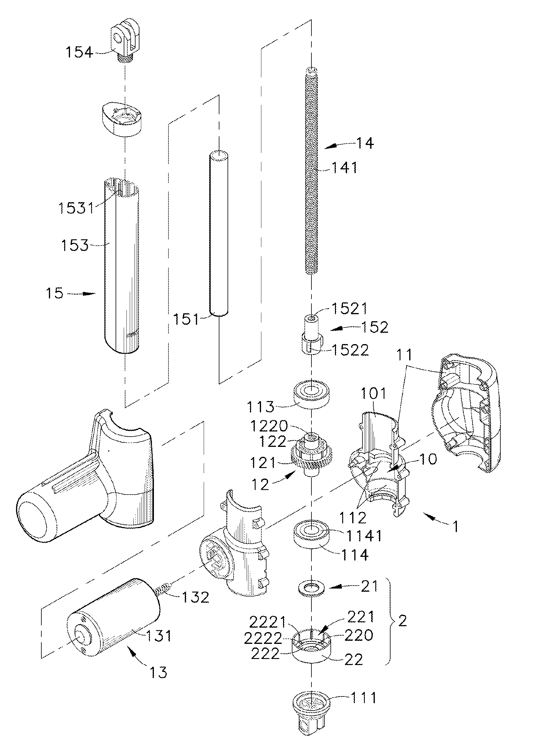
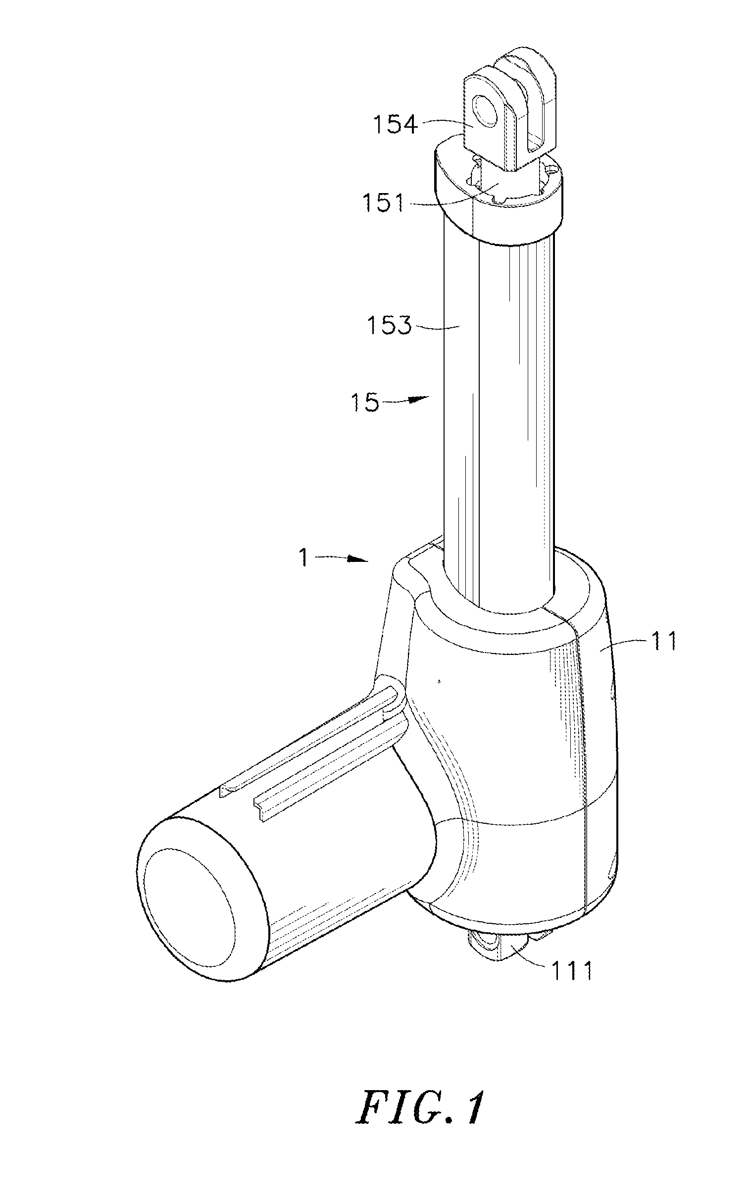
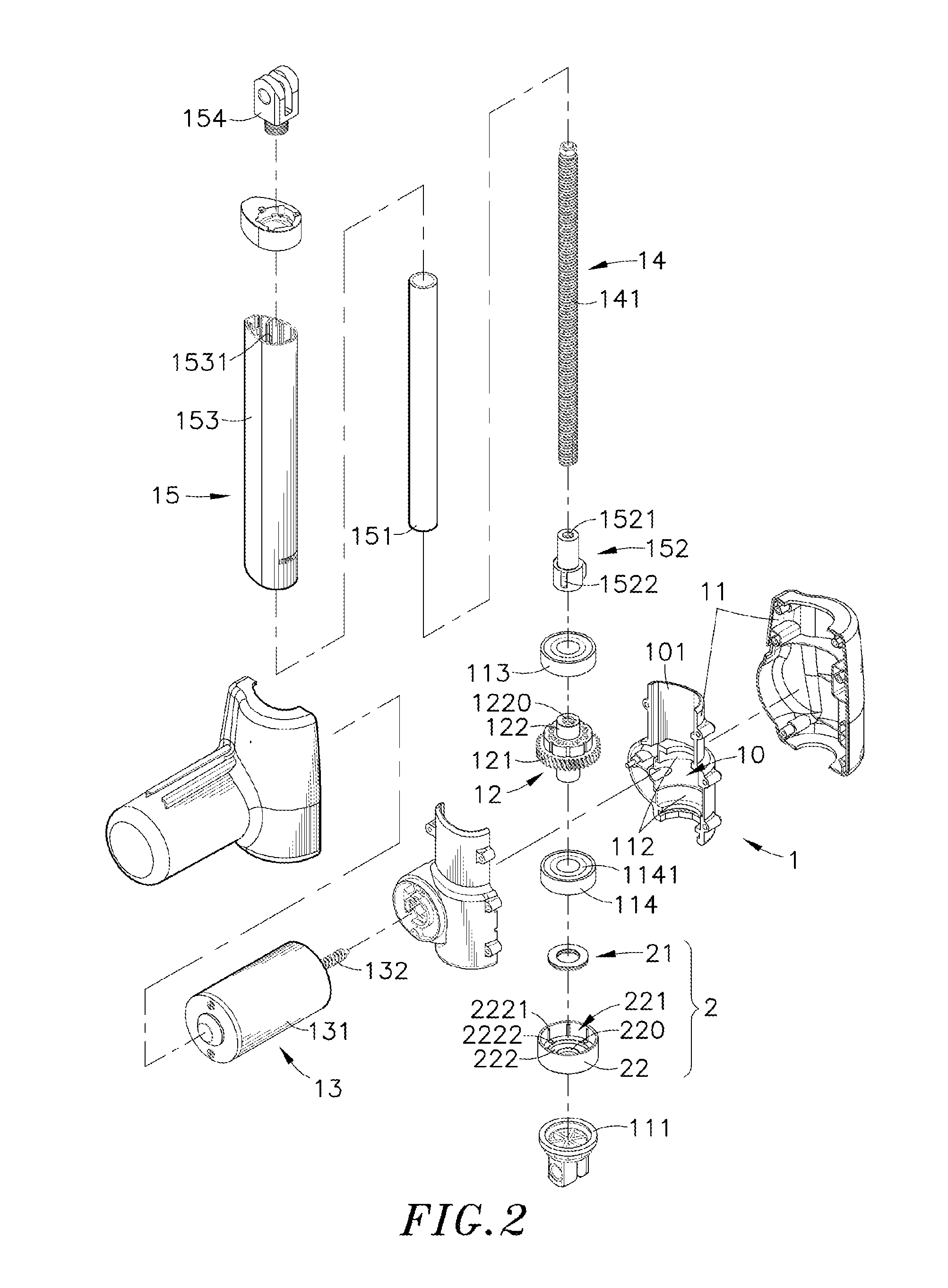
[0017]Referring to FIGS. 1-6, an oblique top elevational view of an improved structure of linear actuator in accordance with the present invention, an exploded view of the improved structure of linear actuator, another exploded view of the improved structure of linear actuator, a sectional side view of the improved structure of linear actuator, an enlarged view of a part of the improved structure of linear actuator and a sectional elevation in an enlarged scale of the thrust bearing of the improved structure of linear actuator are shown. As illustrated, the improved structure of linear actuator comprises an actuator 1 and a stopping mechanism 2.

[0018]The actuator 1 comprises a hollow holder frame 11 consisting of two half shells and defining therein an accommodation chamber 10, an opening 101 at each of opposing top and bottom sides thereof and two locating grooves 112 that are respectively disposed in a middle part of the accommodation chamber 10 and the opening 101 at the bottom s...


PUM


Abstract

An improved structure of linear actuator includes an actuator including a gear set having a friction portion located at the periphery of the gear shaft of a driven gear thereof, a one-way bearing mounted on the gear shaft for rubbing against the friction portion to brake the driven gear from reverse rotation, a driver for driving the gear set and a transmission mechanism including a lead screw coaxially coupled to and rotatable by the gear shaft of the driven gear and a retractable tube assembly coupled to the lead screw and movable by the lead screw between an extended position and a received position, and a stopping mechanism including a thrust bearing coupled to the gear shaft of the driven gear and stoppable against an inner race of the one-way bearing inner race to bear an axial thrust load.

Description

[0001]This application claims the priority benefit of Taiwan patent application number 103220718, filed on Nov. 21, 2014.BACKGROUND OF THE INVENTION[0002]1. Field of the Invention[0003]The present invention relates to linear actuator technology and more particularly, to improved structure of linear actuator, which has a gear shaft of a gear set of the actuator thereof supported in a one-way bearing and a thrust bearing, so that when a driver drives the gear set to rotate a lead screw in moving a retractable tube assembly between an extended position and a received position, the thrust bearing mates with the one-way bearing to bear an axial thrust load, preventing actuator damage and enhancing structural stability.[0004]2. Description of the Related Art[0005]Many different types of linear actuators with different mechanical and transmission designs are known for use in medical or home beds, massage chairs, fitness machines, rehabilitation equipments, door / window openers, lifting mech...

Claims


Application Information

Patent Timeline
IPC IPC(8): F16H25/20F16C19/30F16H25/24
CPCF16H25/2015F16H25/2454F16H2025/2031F16H2025/209F16H2025/204F16C19/305F16C35/077F16C19/32F16C19/545F16H2025/2084F16C19/49
Inventor TSENG, HSIEN-TE
Owner MOTECK ELECTRIC CORP
Learn More