
Lightweight hollow particles for use in cementing

a technology of light weight hollow particles and cementing, which is applied in the direction of cementware, sealing/packing, and well accessories, etc., can solve the problems of reducing the quality of cement, and not meeting all the requirements stated abov

Active Publication Date: 2016-05-19
BAKER HUGHES HLDG LLC
View PDF8 Cites 8 Cited by
  • Summary
  • Abstract
  • Description
  • Claims
  • Application Information

AI Technical Summary

Benefits of technology

The patent describes a way to make a hollow particle for use in cementing. This particle is made by heating calcium carbonate, clay, and an inorganic material like glass to a high temperature. As the inorganic material melts, gases are released and the material expands and forms a hollow sphere. The presence of clay helps keep the hollow core rigid at high temperatures. A composite containing this hollow particle has cement grains adhered to it or embedded in its surface. This composite is easier to handle and use than traditional extenders, which are separate components in a mix containing powder cement. The use of this hollow particle can make cementing more efficient and effective in wellbore construction.

Problems solved by technology

Fractures may form in the zone or formation and the cementitious slurry may be lost in such fractures.
Although each of these methods has produced lightweight cementitious slurries with some degree of success, none of these methods fulfill all the requirements stated above.
For instance, while water extended cements render slurries having lower densities, they also produce lower quality cement.
Foamed cementitious slurries present challenges in design and field execution, require special equipment (for example, high pressure cryogenic pumps and liquid nitrogen tanks) and highly skilled personnel.
Further, when nitrogen is used, the base cement slurry can only be expanded by 25-30% while retaining the mechanical properties of the original slurry.
Hollow pozzolanic spheres are generally unsuitable for cement slurries with densities lower than 10.0 ppg and typically will not resist hydrostatic pressures higher than 3,000 psi.
Further, since such spheres are a by-product of coal burning operations, they exhibit significant variations in densities and a wide particle size distribution, which increases the difficulty of job design.
Borosilicate glass spheres exhibit a much tighter particle size distribution but their extremely low density challenges job design and field execution.
These additives do not contribute to, and may hinder, the development of strength and other desirable properties in the cement.

Method used


Image

  • Lightweight hollow particles for use in cementing
  • Lightweight hollow particles for use in cementing
  • Lightweight hollow particles for use in cementing

Examples


example 1

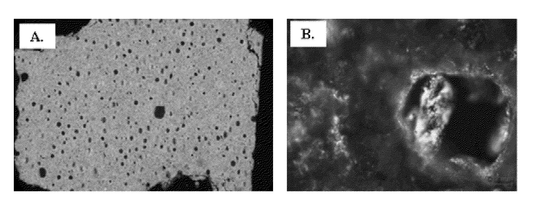
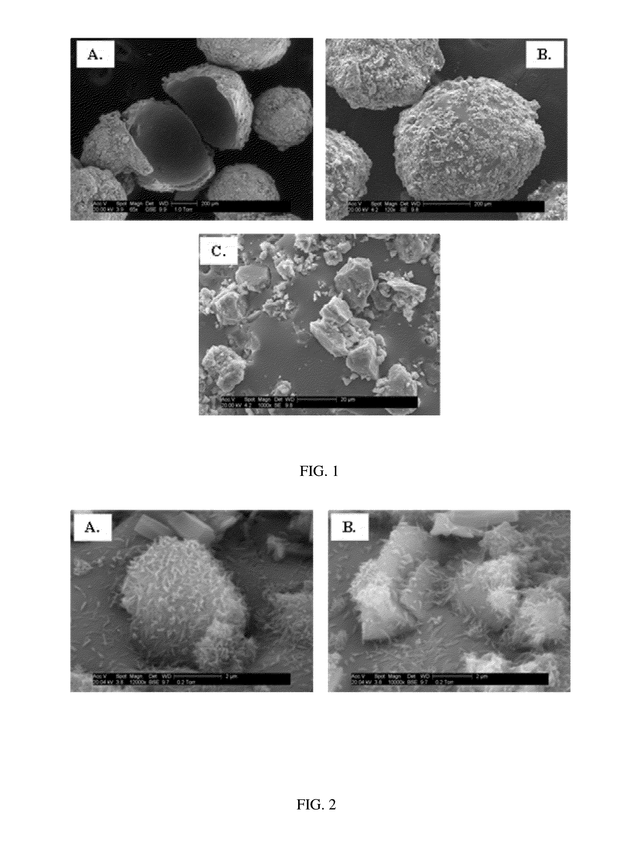
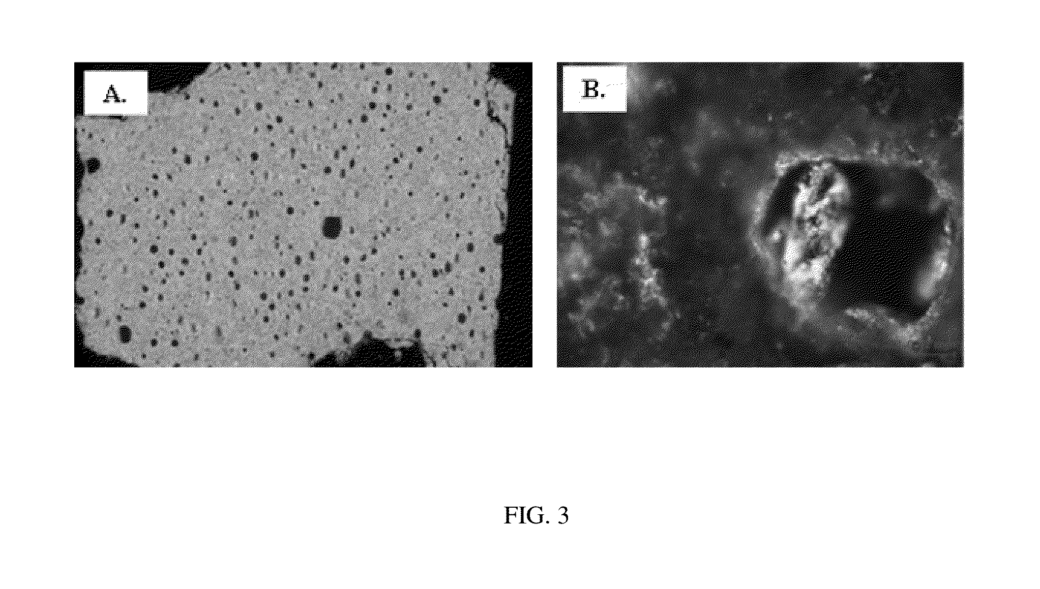
[0056]A 1.5% carboxymethyl cellulose (CMC) in water solution was prepared by dissolving 1.5 grams of CMC as binder in 98.5 grams of deionized water. A lightweight precursor composition was prepared by mixing 83 g borosilicate glass and 5 g bentonite and then adding 12 g calcium carbonate in a jar mill for about one hour. Prior to mixing the bentonite, glass and calcium carbonate were sieved to be less than 325 mesh. About 200.0 grams of the lightweight particle powder was placed in the pan of the lab scale version of an Eirich mixer. Using an atomizer, 57.0 grams of the 1.5% CMC solution was sprayed onto the powder while the pan was rotated at 74 rpm and the contra rotating impeller at 1250 rpm. The binder solution and powder were allowed to mix at this mixer setting for 2 minutes to form spheres. To prevent the spheres from agglomerating, 40.0 grams of bentonite was added to the pan as a parting agent and this was rotated, without the impeller, for 1 minute. The spheres were then r...

example 2

[0058]This Example describes the preparation of hollow spheres having an active surface. A 1.5% CMC in water solution was prepared by dissolving 1.5 grams of CMC in 98.5 grams of deionized water. About 200.0 grams of lightweight particle precursor powder (<325 mesh) was placed in the pan of the lab scale version of an Eirich mixer. Using an atomizer, 57.0 grams of the 1.5% CMC solution was sprayed onto the powder while the pan was rotated at 74 rpm and the contra rotating impeller at 1250 rpm. The binder solution and powder were allowed to mix at this mixer setting for 2 minutes to form spheres. 600 g of cement powder was added to the pan as the parting agent and this was rotated, without the impeller, for 1 minute. Once dried in a vacuum oven at 100° C. for 4 hours, the spheres were heat treated at a rate of 10° C. / min to 800° C. for 20 minutes in a muffle furnace.

[0059]During the heat treatment, while the glassy spheres were semi-molten, cement grains were embedded in the outer su...

example 3

[0061]Following the procedure of Example 1, hollow microspheres were prepared using varying percentages of bentonite clay and glass. Strength of the hollow microspheres was obtained using an Instron 3345 Load Frame to determine the maximum loading the particles could withstand before fracture (each loading being an average of the max loading of 20 particles) and densities were obtained using a Micromeretics AccuPyc 1330 Gas Pycnometer. The results are set forth in Table 1 below:

Table 1

[0062]

TABLE 1Composition versus strength and density of hollow spheres.%%%SDMax LoadGlassBentoniteCaCO3(g / cc)(lbs)835120.771.47810121.673.85632121.856.85038122.1019.6

Table 1 demonstrates that higher percentages of bentonite cause the glassy composition to resist expansion and produce less expanded lightweight particles with higher strength and higher density.


PUM

PropertyMeasurementUnit
hydrostatic pressuresaaaaaaaaaa
densitiesaaaaaaaaaa
particle sizeaaaaaaaaaa

Abstract

A lightweight composite having an activated surface contains a lightweight hollow core particle having cement grains which may be adhered to the hollow core or embedded in the surface of the hollow core. The hollow core particle may be prepared from calcium carbonate and a mixture of clay, such as bentonite, and a glassy inorganic material, such as glass spheres, glass beads, glass bubbles, borosilicate glass and fiberglass.

Description

[0001]This application is a divisional application of U.S. patent application Ser. No. 13 / 328,032, filed on Dec. 16, 2011, now U.S. Pat. No. 9,033,040.FIELD OF THE INVENTION[0002]A lightweight particle and composites containing the lightweight particle as hollow core and cement grains adhered to and / or embedded in the hollow core for use in cementing a casing to a wellbore.BACKGROUND OF THE INVENTION[0003]Hydraulic cements are cements that set and develop compressive strength due to hydration. Such cements can therefore be set under water. As such, hydraulic cements are often used for cementing pipes or casings within a wellbore.[0004]In a typical cementing operation, casing is lowered into the wellbore. A cementitious slurry is then pumped into the casing and a plug of fluid, such as drilling mud or water, is then pumped behind the cement slurry in order to force the cement up into the annulus between the exterior of the casing and the borehole. The cement slurry is then allowed to...

Claims


Application Information

Patent Timeline
Patent Type & Authority Applications(United States)
IPC IPC(8): C09K8/473
CPCC09K8/473C04B14/104C04B14/24C04B18/027C04B20/12C04B38/009C04B38/08C09K8/467E21B33/13Y10T428/2991Y10T428/2996
Inventor PISKLAK, THOMAS J.MORILLO, ELIZABETH G.QU, QI
Owner BAKER HUGHES HLDG LLC
Learn More