Vehicle Body Front Structure

a front structure and vehicle technology, applied in the direction of roofs, bumpers, instruments, etc., can solve the problems of large number of components for attaching the radar unit, and the radar unit cannot move back upon collision from diagonally abov

Inactive Publication Date: 2016-05-19
SUZUKI MOTOR CORP
View PDF12 Cites 34 Cited by
  • Summary
  • Abstract
  • Description
  • Claims
  • Application Information

AI Technical Summary

Benefits of technology

[0008]In order to solve the foregoing problems, the present invention is directed to a vehicle body front structure comprising a radar unit, and the vehicle body front structure further comprises a bumper member that extends in a vehicle width direction on a rear side with respect to a front bumper and supports the front bumper, a hood lock member that is provided parallel to the bumper member on a vehicle rear side with respect to the bumper member above the bumper member, a hood lock being attached to the hood lock member, and a radar bracket that is disposed between the bumper member and the hood lock member, the radar unit being fixed to the radar bracket, wherein the radar bracket includes an upright portion that is attached to the bumper member and extends upward from the bumper member, the radar unit being fixed to the upright portion, an oblique portion that is continuous with an upper end of the upright portion, extends toward a vehicle rear side and upward, and is attached to the hood lock member, a first deformation portion that is formed at a boundary between the upright portion and the oblique portion and facilitates a change in an angle between the upright portion and the oblique portion, and a second deformation portion that is formed at a position of the oblique portion at which the oblique portion is attached to the hood lock member and facilitates a change in a direction in which the oblique portion extends from the hood lock member, and wherein a space that can accommodate at least a portion of the radar unit is formed under the oblique portion on a rear side with respect to the upright portion.
[0009]With the present invention, the radar bracket provided with the oblique portion in which the deformation portions are formed is disposed between the bumper member and the hood lock member, thus making it possible to form the space under the oblique portion on the vehicle rear side with respect to the upright portion. When an impact is applied from the front side with respect to the vehicle or diagonally above the vehicle, the oblique portion is inclined toward the vehicle rear side and lower side around the first deformation portion and the second deformation portion as starting points. At this time, the radar unit can move back toward the vehicle rear side and lower side and at least a portion of the radar unit can be accommodated in the above-noted space, thus making it possible to smoothly incline the oblique portion of the radar bracket and to reduce the impact applied to a collision object. In particular, since the radar bracket is provided with the oblique portion, not only the impact from the front side with respect to the vehicle but also the impact from diagonally above the vehicle can be absorbed by the oblique portion.
[0010]It is preferable that the radar bracket further includes, a third deformation portion that is formed at a boundary between the bumper member and the upright portion and that facilitates a change in a direction in which the upright portion extends from the bumper member, and a fourth deformation portion that is formed at a boundary between the upright portion and the radar unit and that facilitates deformation of the upright portion near the radar unit.

Problems solved by technology

JP 2007-30535A, there is a problem in that a large number of components for attaching the radar unit are required.
JP 2007-30535A copes only with collisions from the front side with respect to a vehicle, there is the problem that the radar unit cannot move back upon collision from diagonally above, for example.

Method used


Image

  • Vehicle Body Front Structure
  • Vehicle Body Front Structure
  • Vehicle Body Front Structure

Examples


Embodiment Construction

[0029]Hereinafter, a preferred embodiment of the present invention will be described in detail with reference to the accompanying drawings. The dimensions, materials, and other specific numerical values described in this embodiment are merely examples for facilitating the understanding of the present invention, and are not to be construed as limiting the invention unless otherwise stated. It should be noted that elements constituting substantially identical functions and configurations are denoted by identical reference numerals in the present specification and the drawings, and hence redundant description has been omitted. Also, illustration of elements that are not directly relevant to the present invention has been omitted.

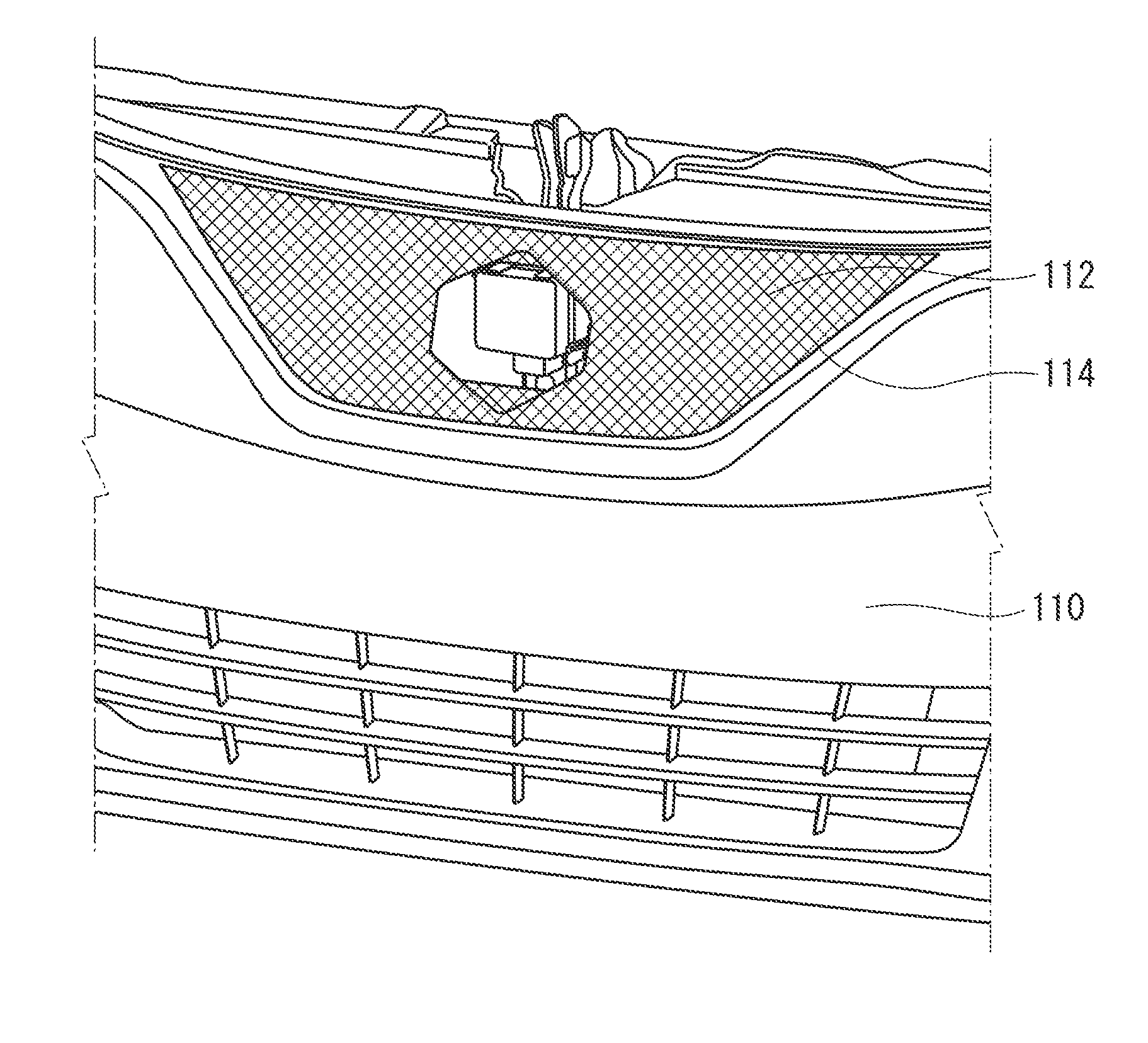
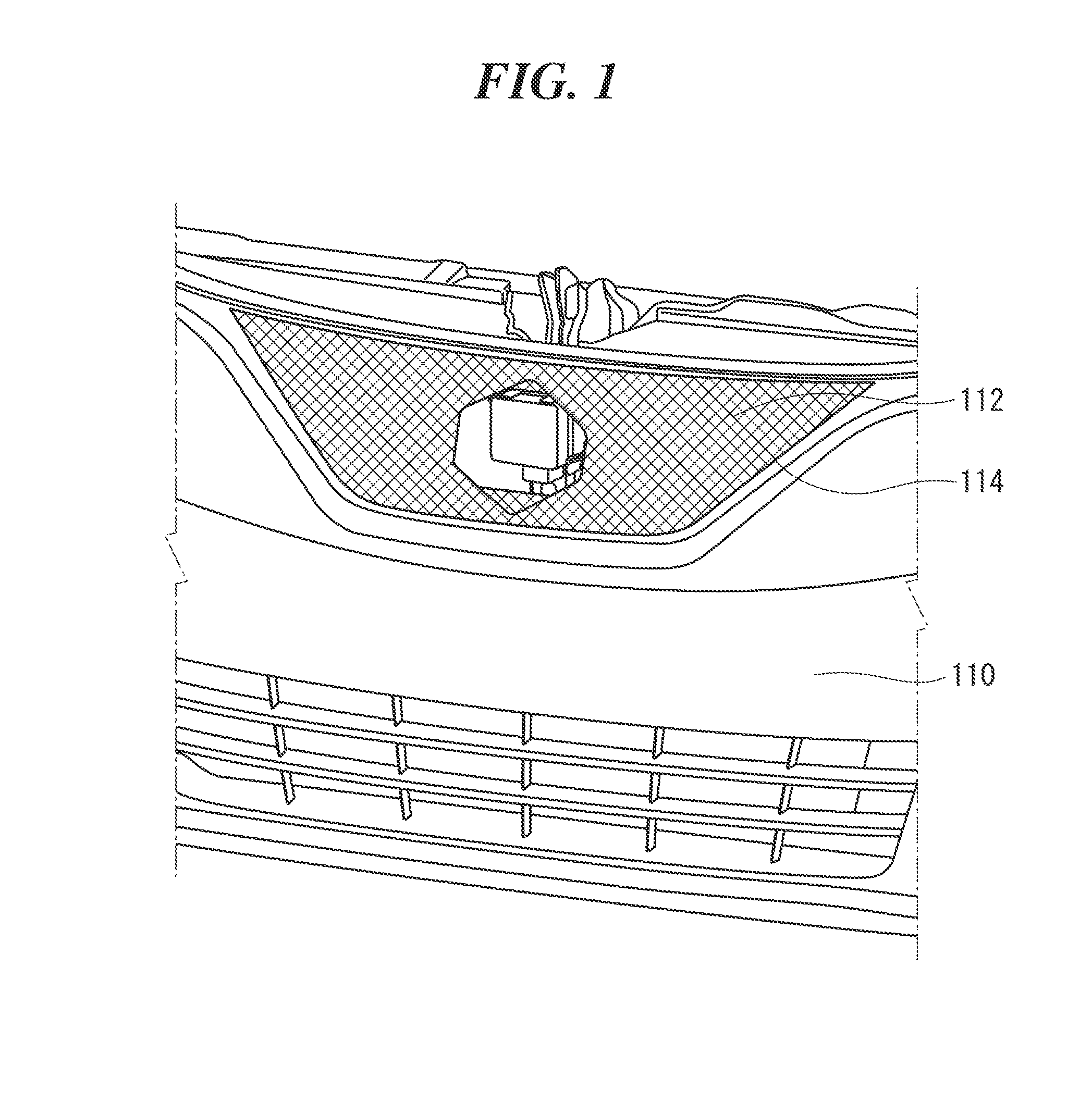
[0030]FIG. 1 is an enlarged view of the front surface of a vehicle in which a vehicle body front structure according to this embodiment is used. FIG. 2 is a perspective view illustrating a state in which a front bumper and a front grill are removed from the veh...


PUM


Abstract

A vehicle body front structure comprises a radar bracket disposed between a bumper member and a hood lock member. The radar bracket includes an upright portion to which a radar unit is fixed and oblique portions that are continuous with an upper end of the upright portion and extend toward a vehicle rear side and upward, and a space is formed under the oblique portions on a rear side with respect to the upright portion. At a boundary between the upright portion and the oblique portions, first deformation portions are formed that facilitate deformation at this boundary, and at attachment positions of the oblique portions at which the oblique portions are attached to the hood lock member, second deformation portions are formed that facilitate deformation at these attachment positions.

Description

CROSS-REFERENCE TO RELATED APPLICATION[0001]This application is based upon and claims the benefit of priority from the prior Japanese Patent Application No. 2014-232687, filed on Nov. 17, 2014, the entire contents of which are incorporated herein by reference.FIELD[0002]The present invention relates to a vehicle body front structure comprising a radar unit.BACKGROUND[0003]In recent years, an object detection device such as an ACC (Adaptive Cruise Control System) millimeter-wave radar unit that detects the presence or absence of an object in a traveling direction of a vehicle, a relative distance between vehicles, and the like has been mounted in the vehicle body front portion of vehicles such as automobiles. Such a radar unit is mounted on a vehicle rear side with respect to a front bumper, and a radar detection area of the radar unit radially extends from there toward a front side with respect to the vehicle body. Strict conditions are required for radio wave transmission in the de...

Claims


Application Information

Patent Timeline
Patent Type & Authority Applications(United States)
IPC IPC(8): B62D25/08G01S13/93B62D25/12G01S13/931
CPCB62D25/085G01S2013/9389G01S13/931B62D25/12B62D25/08G01S2013/9327G01S2013/93275G01S2013/93271G01S7/027B60R19/02G01S7/02
Inventor TANEDA, KODAI
Owner SUZUKI MOTOR CORP
Why Eureka
Try Eureka