
Multi-gas centrally cooled showerhead design

a central cooling, shower head technology, applied in the direction of chemically reactive gas growth, crystal growth process, polycrystalline material growth, etc., can solve the problems of precursor material deposition on the hot surface, break-down of precursor materials,

Inactive Publication Date: 2016-05-19
APPLIED MATERIALS INC
View PDF0 Cites 79 Cited by
  • Summary
  • Abstract
  • Description
  • Claims
  • Application Information

AI Technical Summary

Problems solved by technology

Interaction of the process gases with the hot hardware components, which are often found in the processing zone of an LED or LD forming reactor, will generally cause the precursor to break-down and deposit on these hot surfaces.
The deposition of the precursor materials on the hot surfaces can be especially problematic when it occurs in or on the precursor distribution components, such as the showerhead.

Method used


Image

  • Multi-gas centrally cooled showerhead design
  • Multi-gas centrally cooled showerhead design
  • Multi-gas centrally cooled showerhead design

Examples


Embodiment Construction

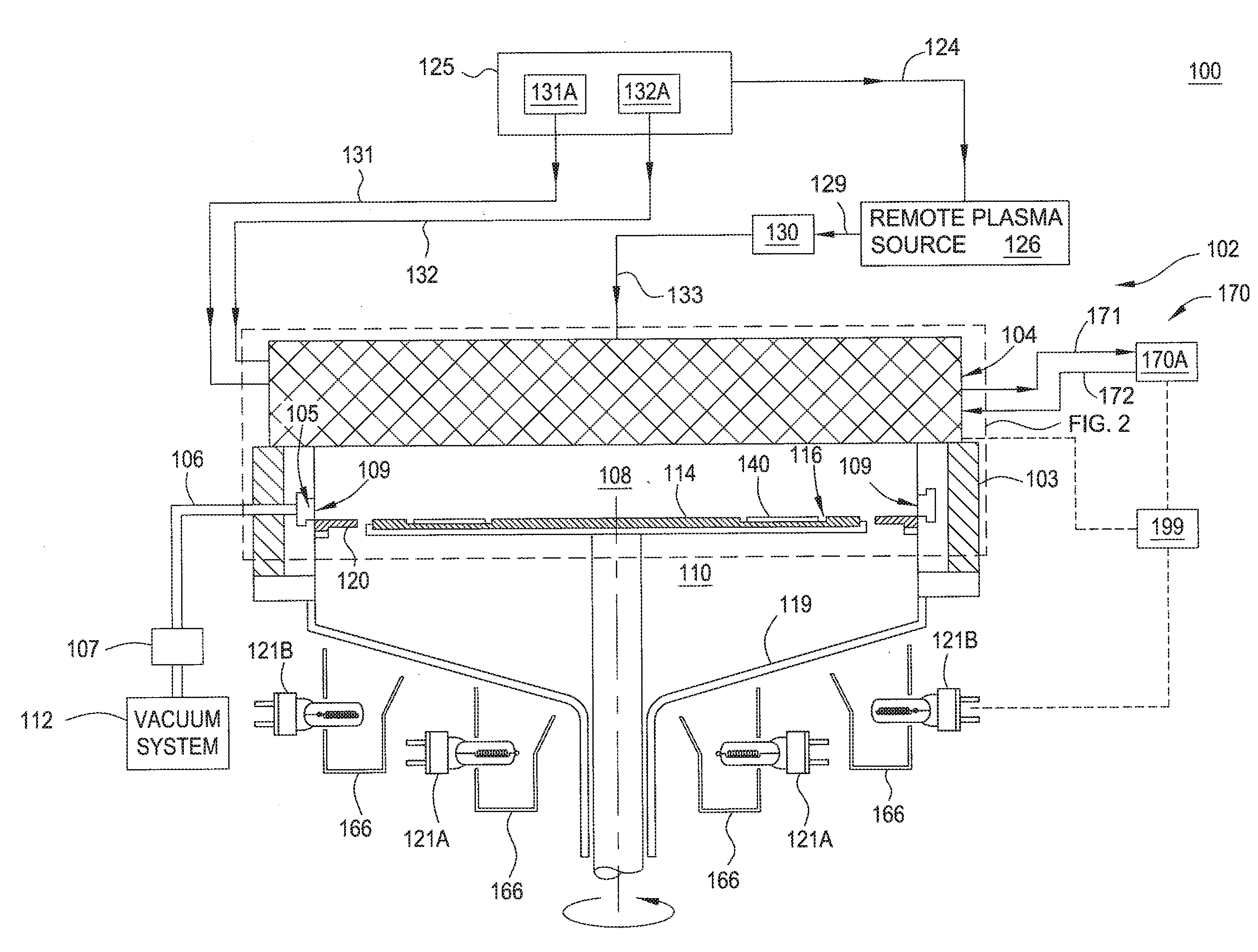
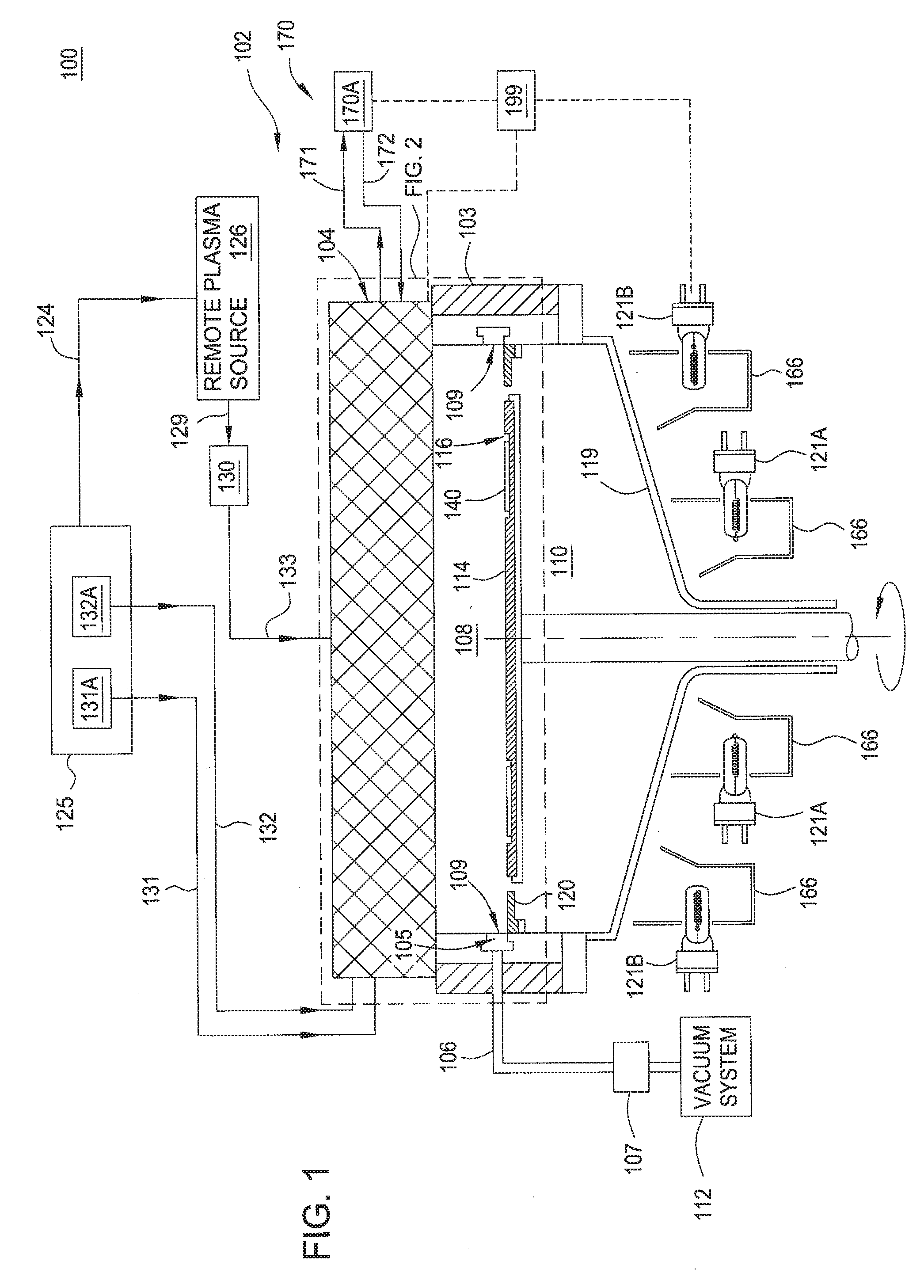
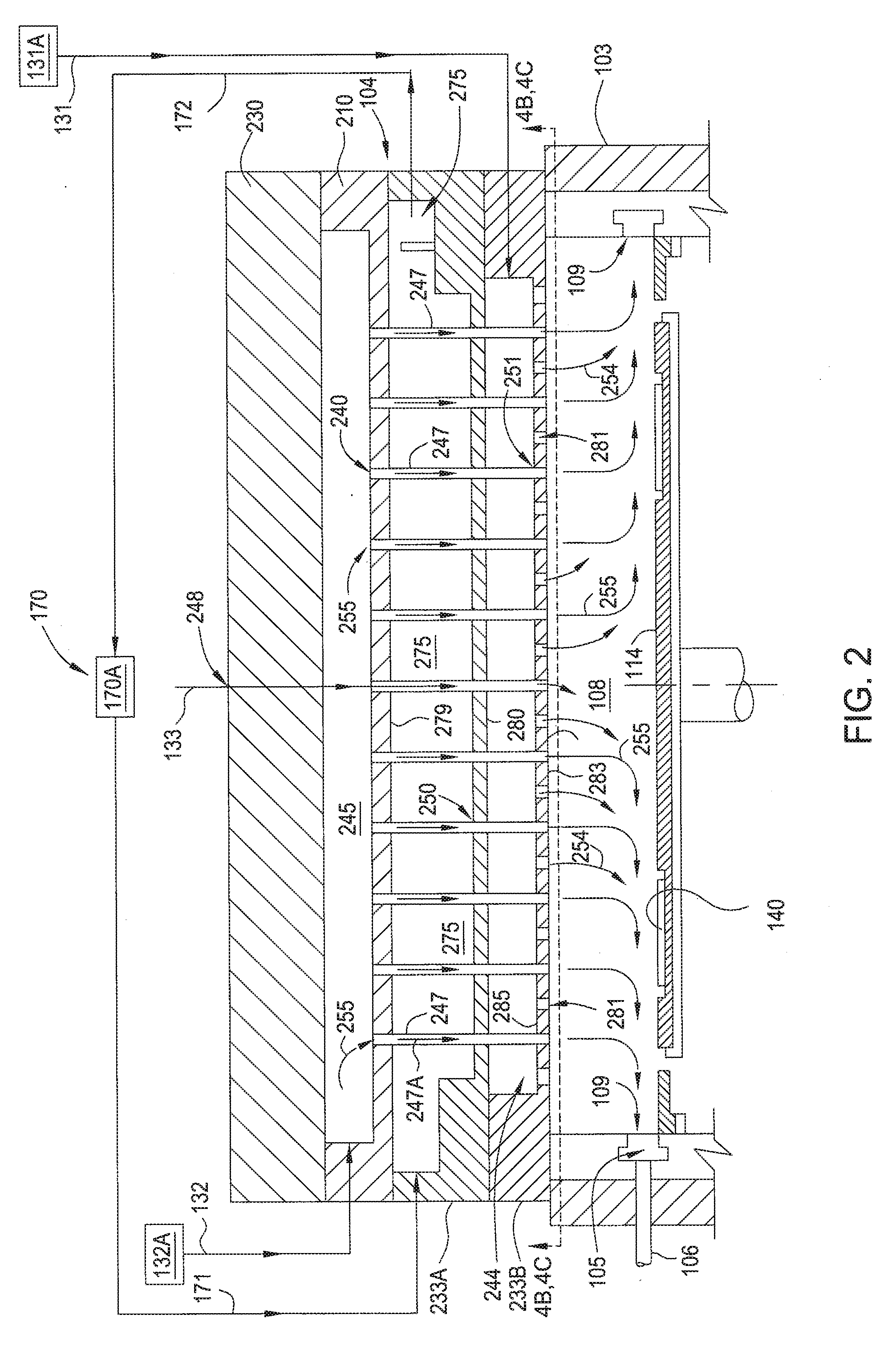
[0022]A method and apparatus that may be utilized for chemical vapor deposition and / or hydride vapor phase epitaxial deposition are provided. The apparatus generally include a lower bottom plate and an upper bottom plate defining a first plenum. The upper bottom plate and a mid-plate positioned above the upper bottom plate define a heat exchanging channel. The mid-plate and a top plate positioned above the mid-plate define a second plenum. A plurality of gas conduits extend from the second plenum through the heat exchanging channel and the first plenum. The method generally includes flowing a first gas through the first plenum into a processing region and flowing a second gas through the second plenum into a processing region. A heat exchanging fluid is introduced to a heat exchanging channel disposed between the first plenum and the second plenum. The temperature of the first gas is greater than the temperature of the second gas when the first gas and the second gas enter the proce...


PUM

PropertyMeasurementUnit
diameteraaaaaaaaaa
temperatureaaaaaaaaaa
sizeaaaaaaaaaa

Abstract

A method and apparatus for chemical vapor deposition and / or hydride vapor phase epitaxial deposition are provided. The apparatus generally include a lower bottom plate and an upper bottom plate defining a first plenum. The upper bottom plate and a mid-plate positioned above the upper bottom plate define a heat exchanging channel. The mid-plate and a top plate positioned above the mid-plate define a second plenum. A plurality of gas conduits extend from the second plenum through the heat exchanging channel and the first plenum. The method generally includes flowing a first gas through a first plenum into a processing region, and flowing a second gas through a second plenum into a processing region. A heat exchanging fluid is introduced to a heat exchanging channel disposed between the first plenum and the second plenum. The first gas and the second gas are then reacted to form a film on a substrate.

Description

CROSS-REFERENCE TO RELATED APPLICATIONS[0001]This application claims benefit of U.S. patent application Ser. No. 13 / 500,948, filed Oct. 23, 2012, which is a national phase entry of International Patent Application No. PCT / US2010 / 051961, filed Oct. 8, 2010, which claims benefit of U.S. Provisional Patent Application No. 61 / 250,472, filed Oct. 9, 2009. Each of the aforementioned applications is herein incorporated by reference.BACKGROUND OF THE INVENTION[0002]1. Field of the Invention[0003]Embodiments of the present invention generally relate to methods and apparatus for chemical vapor deposition (CVD) on a substrate, and, in particular, to a showerhead design for use in metal organic chemical vapor deposition and / or hydride vapor phase epitaxy (HVPE).[0004]2. Description of the Related Art[0005]Group III-V films are finding greater importance in the development and fabrication of a variety of semiconductor devices, such as short wavelength light emitting diodes (LEDs), laser diodes (...

Claims


Application Information

Patent Timeline
Patent Type & Authority Applications(United States)
IPC IPC(8): B05B1/18
CPCB05B1/18H01L21/67115C23C16/4411C23C16/455C23C16/45514C23C16/45565C23C16/45572C23C16/45574C23C16/45576C30B25/14C30B29/403H01L21/0254H01L21/0262
Inventor SONG, EDDY J.
Owner APPLIED MATERIALS INC
Learn More